Are you an analogue photographer looking for a different way to present your images? Have you ever thought about shooting a sequence of stills and reanimating them in a zoetrope, an optical device from the Victorian era that pre-figured cinema? That is exactly what I decided to do as a project to occupy myself during the zombie apocalypse Covid-19 lockdown. Contact prints are aesthetically pleasing in themselves, and I wanted to tap into the history of the zoetrope by creating a movie-like continuous filmstrip of sequential images and bringing them to life.

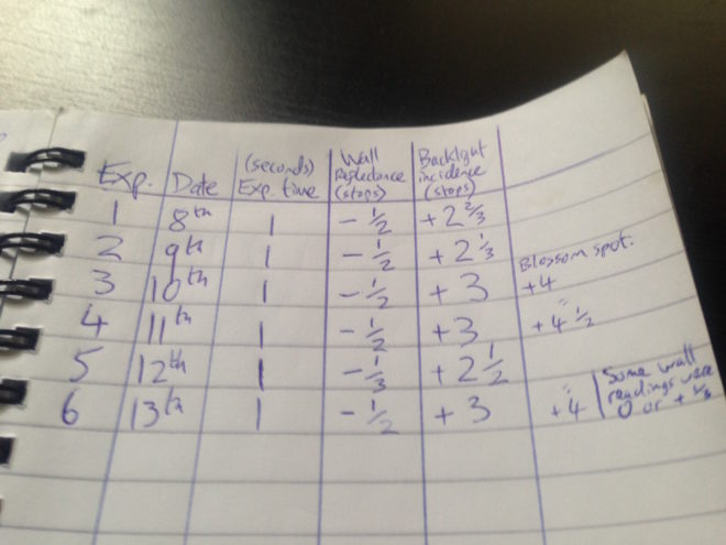
In the first part of my blog about this project, I covered the background and setting up a time-lapse of my cherry tree as content for the device. This weekend I shot the final image of the time-lapse, the last of the blossom having dropped. No-one stole my camera while it sat in my front garden for three weeks, and I was blessed with consistently sunny weather until the very last few days, when I was forced to adjust the exposure time to give me one or two extra stops. I’ll be interested to see how the images have come out, once I can get into the darkroom.
Meanwhile, I’ve been constructing the zoetrope itself, following this excellent article on Reframing Photography. Based on this, I’ve put together my own instructions specifically for making a device that holds 18 frames of contact-printed 35mm film. I chose a frame count of 18 for a few reasons:
- The resultant diameter, 220mm, seemed like a comfortable size, similar to a table lamp.
- Two image series of 18 frames fit neatly onto a 36 exposure film.
- Negatives are commonly cut into strips of six frames for storage and contact-printing, so a number divisible by six makes constructing the image loop a little more convenient.
You Will Need
- Contact sheet containing 18 sequential 35mm images across three rows
- A1 sheet of 300gsm card, ideally black
- PVA glue
- Ruler (the longer the better)
- Set square
- Compass
- Pencil & eraser
- Scissors
- Craft knife or stanley knife
- Paper clips or clothes pegs for clamping while glue dries
- Rotating stand like a lazy susan or record player
Making the image loop
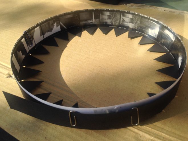
First, cut out the three rows of contact prints, leaving a bit of blank paper at one end of each row for overlap. Now glue them together into one long strip of 18 sequential images. The strip should measure 684mm plus overlap, because a 35mm negative or contact print measures 38mm in width including the border on one side: 38×18=684.

Glue the strip together into a loop with the images on the inside. This loop should have a diameter of 218mm. Note that we must make our zoetrope’s drum to a slightly bigger diameter, or the image loop won’t fit inside it. We’ll use our image loop to check the size of the drum; that’s why we’ve made it first. (If you don’t have your images ready yet, use an old contact sheet – as I did – or any strip of paper or light card of the correct size, 35mmx684mm.)
Making the side wall
Cut a strip of the black card measuring 723x90mm. This will be the side wall of your drum. Wrap this strip around your image loop, as tightly as you can without distorting the circular shape of the image loop. Mark where the card strip overlaps itself to find the circumference of the drum, which will be slightly bigger than the 684mm circumference of the image loop. In my case the drum circumference was 688mm – as illustrated in the diagram above. (You can click on it to enlarge it.)

Now we can measure and cut out the slots, one per image. Reframing Photography recommends a 1/8″ width, and initially I went with this, rounding it to 3mm. As with making a pinhole, a smaller slot means a sharper but darker image, while a bigger slot means a brighter but blurrier one. Once my zoetrope was complete, I felt that there was too much motion blur, so I retrofitted it with 1mm slots.
Let’s stick with 3x35mm (the same height as the images) for our slot size. How far apart should the slots be? They need to be evenly spaced around the circumference, so in my case 688÷18=38.2mm, i.e. a gap of 35.2mm between each slot and then 3mm for the slot itself. If your drum circumference is different to mine, you’ll have to do your own maths to work out the spacing.
(It was impossible to measure 38.2mm accurately, but I made a spreadsheet to give me values for the cumulative slot positions to the nearest millimetre: 38, 76, 115, 153, 191, 229, 268, 306, 344, 382, 420, 459, 497, 535, 573, 612, 650 and 688.)
Mark out your 18 slots, positioning them 15mm from the top of the side wall and 40mm from the bottom, then cut them out carefully using a knife and a ruler.

Now you can glue your side wall into a loop, using paper clips or clothes peg to hold it while the glue dries. I recommend double-checking your image loop fits inside beforehand. (Do not glue your image loop into the drum; this way you can swap it out for another image series whenever you like.)
Making the connector
The connector, as the name suggests, will connect the side wall to the base of the drum. (When I made a prototype, I tried skipping this stage, simply building the connecting teeth into the side wall, but this made it much harder to keep the drum a neat circle.)
Go back to your black card and cut another strip measuring 725x60mm. Score it all the way along the middle (i.e. 30mm from the edge) so that it can be folded in two, long-ways. Now cut triangular teeth into one half of the strip. Each triangle should have a 30mm base along the scored line.

As with the side wall, you should check the circumference of the connector to ensure that it will fit around the side wall and image loop, and adjust it if necessary. My connector’s circumference, as shown on the diagram above, was 690mm.
Glue the strip into a loop, clamping it with clips or pegs while it dries. Again, it doesn’t hurt to double-check that it still fits around the side wall first.
Making the base
Use a compass to draw a circle of 220mm in diameter on your remaining card, and cut it out. (If your connector is signficantly different in circumference to mine, divide that circumference by pi [3.14] to find the diameter that will work for you.)
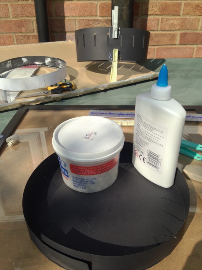
Now you can glue the connector to the base. I suggest starting with a single tooth, putting a bottle of water or something heavy on it to keep it in place while it dries, then do the tooth directly opposite. Once that’s dry, do the ones at 90° and so on. This way you should prevent distortions creeping into the shape of the circle as you go around.

When that’s all dry, apply glue all around the inside of the upright section of the connector. Squish your side wall into a kidney bean shape to fit it inside the connector, then allow it to expand to its usual shape. If you have made it a tight enough fit, it will naturally press against the glue and the connector.
Making it Spin
The critical part of your zoetrope, the drum, is now complete. But to animate the images, you need to make it spin. There are a few ways you can do this:
- Mount it on an old record player, making a hole in the centre of the base for the centre spindle.
- Mount it on a rotating cake decoration stand or lazy susan.
- Make your own custom stand.
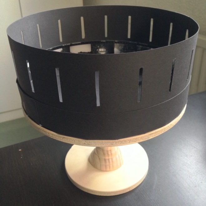
I chose the latter, ordering some plywood discs cut to size, an unfinished candlestick and a lazy susan bearing, then assembling and varnishing them before gluing my drum to the top.


 To make the whole thing a little more fun and primitive, I decided to shoot using