Making a 35mm Zoetrope: The Results

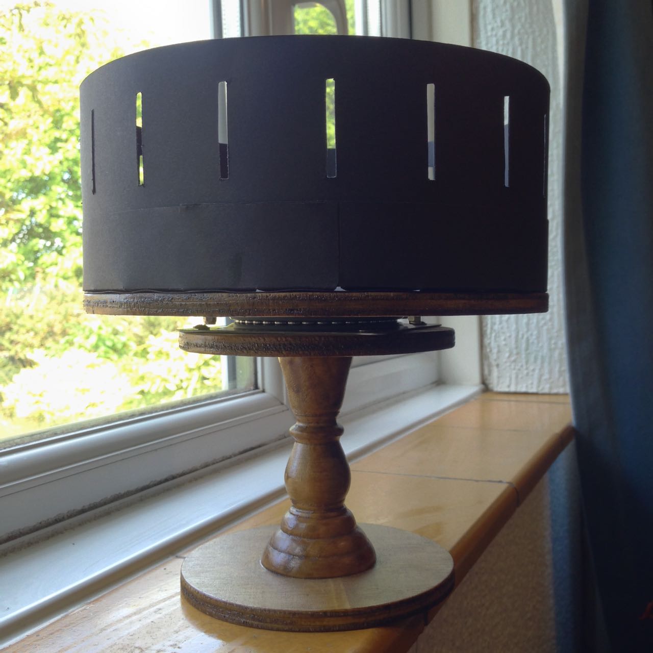
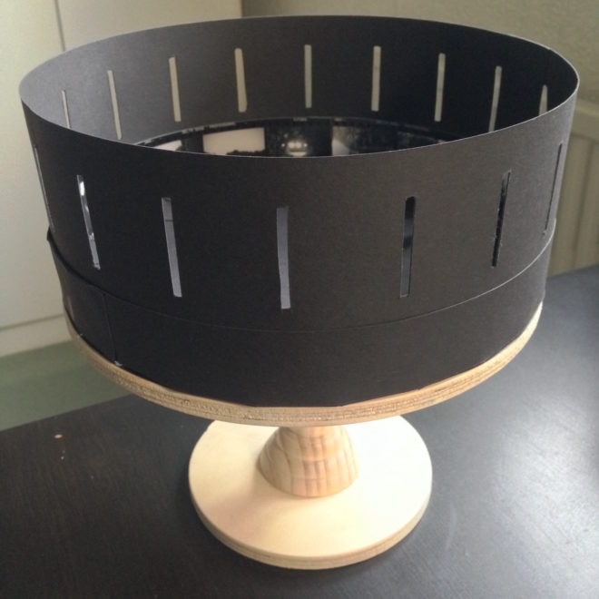
In the early days of lockdown, I blogged about my intentions to build a zoetrope, a Victorian optical device that creates the illusion of a moving image inside a spinning drum. I even provided instructions for building your own, sized like mine to accommodate 18 looping frames of contact-printed 35mm photographs. Well, last week I was finally able to hire my usual darkoom, develop and print the image sequences I had shot over the last five months, and see whether my low-tech motion picture system worked.


Making Mini Movies

Shooting “Sundial”

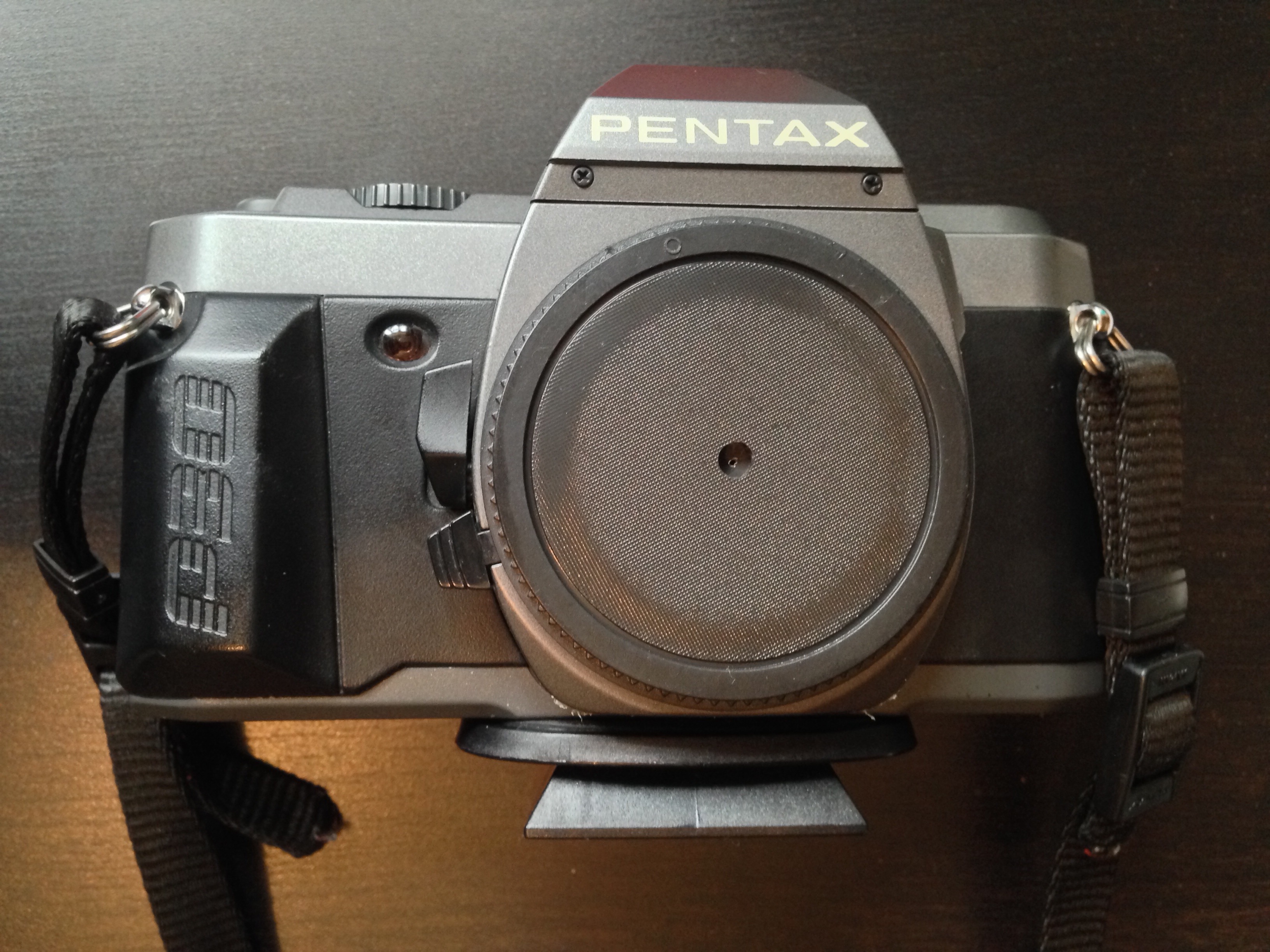
Before I get to the results, let me say a little about the image sequences themselves and how they were created. Because I was shooting on an SLR, the fastest frame rate I could ever hope to record at was about 1fps, so I was limited to time-lapses or stop motion animation.

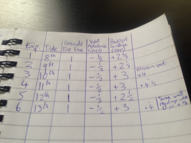
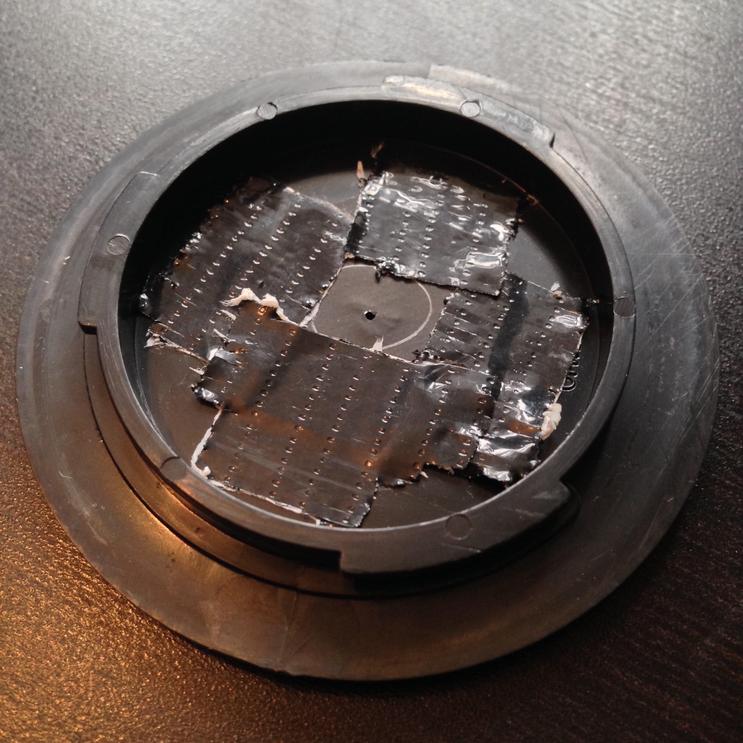
Regular readers may recall that the very first sequence I captured was a time-lapse of the cherry tree in my front garden blossoming. I went on to shoot two more time-lapses, shorter-term ones showing sunlight moving across objects during a single day: a circle of rotting apples in a birdbath (which I call Sundial), and a collection of props from my flatmate’s fantasy films (which I call Barrels). I recorded all the time-lapses with the pinhole I made in 2018.

Filming “Social Distance”

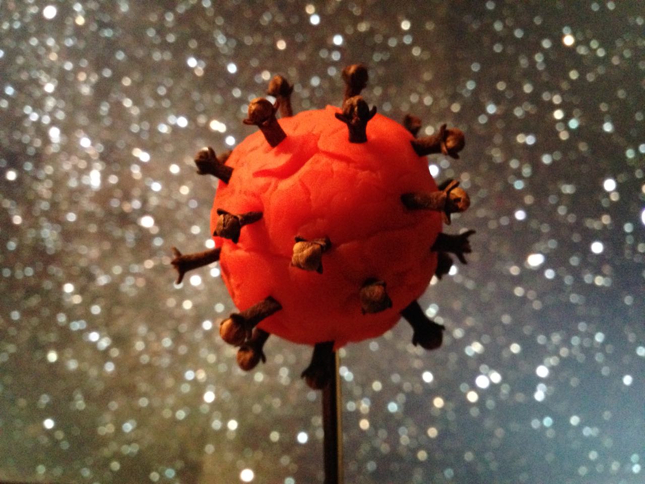
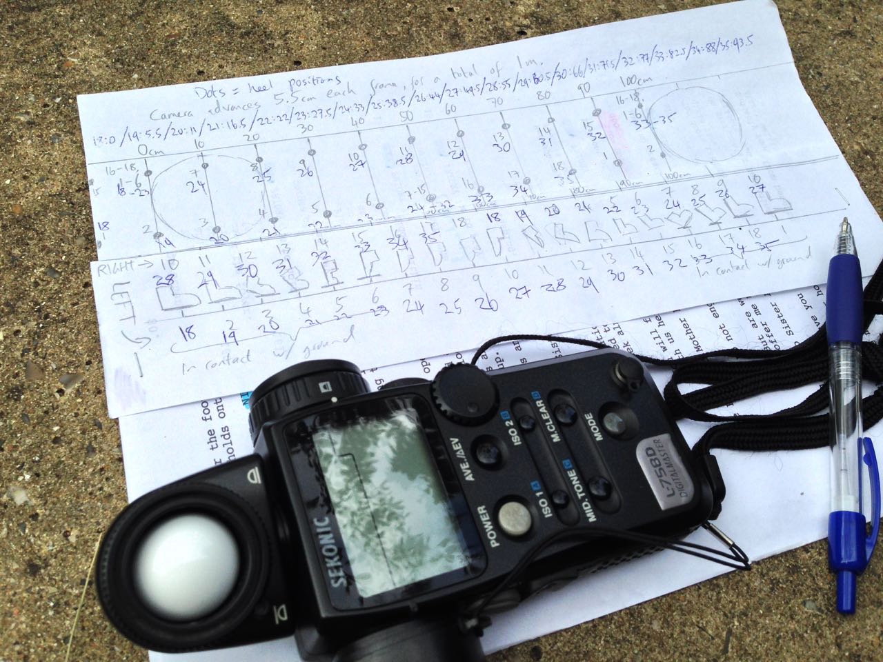
The remaining six sequences were all animations, lensed on 28mm, 50mm or 135mm SMC Pentax-Asahi glass. I had no signficant prior experience of this artform, but I certainly had great fun creating some animated responses to the Covid-19 pandemic. My childish raw materials ranged from Blue Peter-esque toilet roll tubes, through Play-Doh to Lego. Orbit features the earth circling a giant Covid-19, and The Sneeze sees a toilet roll person sternutating into their elbow. Happy Birthday shows a pair of rubber glove hands washing themselves, while Avoidance depicts two Lego pedestrians keeping their distance. 360° is a pan of a room in which I am variously sitting, standing and lying as I contemplate lockdown, and finally Social Distance tracks along with a pair of shoes as they walk past coronavirus signage.

The replacement faces for the toilet paper star of “The Sneeze”

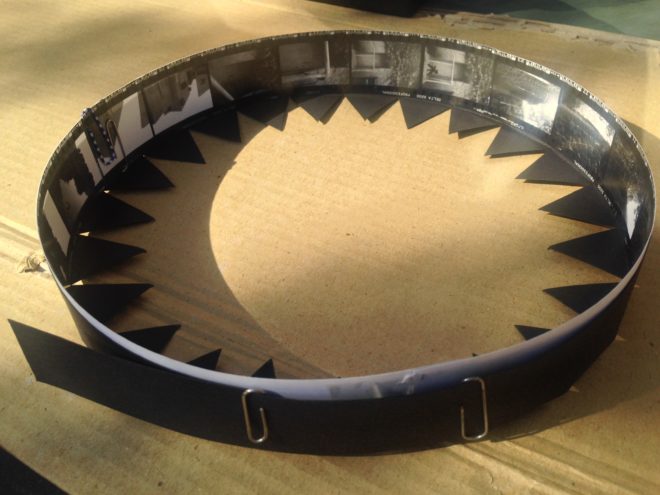
By the time I finished shooting all these, I had already learnt a few things about viewing sequences in a zoetrope, by drawing a simple animation of a man walking. Firstly I discovered that the slots in my device – initially 3mm in width – were too large. I therefore retrofitted the drum with 1mm slots, resulting in reduced motion blur but a darker image, much like reducing the shutter angle on a movie camera. I initially made the mistake of putting my eye right up to the drum when viewing the animation, but this destroys the shuttering effect of the slots. Instead the best results seem to be obtained with a viewing distance of about 30cm (1ft).

I could already see where I might have made mistakes with my photographed sequences. The hand-drawn man was bold and simple; it looked best in good light, by a window or outdoors, but it was clear enough to be made out even if the light was a bit poor and there was too much motion blur. Would the same be said of my 35mm sequences?


Postproduction

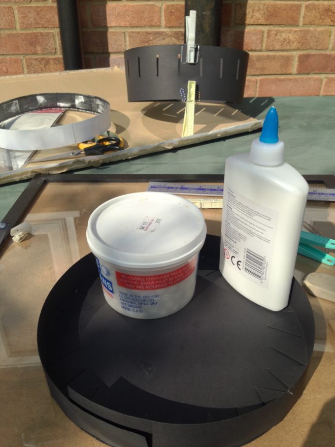
I contact-printed the nine photographic sequences in the usual way, each one producing three rows of six frames on a single sheet of 8×10″ Ilford MG RC paper. In theory, all that was left was to cut out these rows and glue them together.

In practice, I had managed to screw up a few of the sequences by fogging the start of the film, shooting a frame with bad exposure, or some other act of shameful incompetence. In such cases I had to edit much like filmmakers did before the invention of digital NLEs – by cutting the strips of images, excising the rotten frames and taping them back together. I even printed some of the sequences twice so that I could splice in duplicate frames, where my errors had left a sequence lacking the full 18 images. (This was effectively step-printing, the obsolete optical process by which a shot captured at 24fps could be converted to slow motion by printing each frame twice.)

"Blossom"

Once the sequences were edited, I glued them into loops and could at last view them in the zoetrope. The results were mixed.

Barrels fails because the moving sunlight is too subtle to be discerned through the spinning slots. The same is partly true of Sundial, but the transient glare caused by the sun reflecting off the water at its zenith gives a better sense of motion. Blossom shows movement but I don’t think an uninitiated viewer would know what they were looking at, so small and detailed is the image. Orbit suffers from smallness too, with the earth and Covid-19 unrecognisable. (These last two sequences would have benefitted from colour, undoubtedly.)

The planet Covid-19 (as seen by my phone camera) made from Play-Doh and cloves

I’m very pleased with the animation of Social Distance, though I need to reprint it brighter for it to be truly effective. You can just about make out that there are two people passing each other in Avoidance, but I don’t think it’s at all clear that one is stepping into the road to maintain a safe distance from the other. Happy Birthday is a bit hard to make out too. Similarly, you can tell that 360° is a pan of a room, but that’s about it.

Perhaps the most successful sequence is The Sneeze, with its bold, white toilet roll man against a plain black background.

"Happy Birthday"


Conclusions

Any future zoetrope movies need to be bold, high in contrast and low in detail. I need to take more care to choose colours that read as very different tones when captured in black and white.

Despite the underwhelming results, I had a great time doing this project. It was nice to be doing something hands-on that didn’t involve sitting at a screen, and it’s always good to get more practice at exposing film correctly. I don’t think I’ll ever make an animator though – 18 frames is about the limit of my patience.

My light meter lies beside my animation chart for the walking feet in “Social Distance”.


Making a 35mm Zoetrope: The Results

How to Make a Zoetrope for 35mm Contact Prints

Are you an analogue photographer looking for a different way to present your images? Have you ever thought about shooting a sequence of stills and reanimating them in a zoetrope, an optical device from the Victorian era that pre-figured cinema? That is exactly what I decided to do as a project to occupy myself during the zombie apocalypse Covid-19 lockdown. Contact prints are aesthetically pleasing in themselves, and I wanted to tap into the history of the zoetrope by creating a movie-like continuous filmstrip of sequential images and bringing them to life.

In the first part of my blog about this project, I covered the background and setting up a time-lapse of my cherry tree as content for the device. This weekend I shot the final image of the time-lapse, the last of the blossom having dropped. No-one stole my camera while it sat in my front garden for three weeks, and I was blessed with consistently sunny weather until the very last few days, when I was forced to adjust the exposure time to give me one or two extra stops. I’ll be interested to see how the images have come out, once I can get into the darkroom.

Meanwhile, I’ve been constructing the zoetrope itself, following this excellent article on Reframing Photography. Based on this, I’ve put together my own instructions specifically for making a device that holds 18 frames of contact-printed 35mm film. I chose a frame count of 18 for a few reasons:

  1. The resultant diameter, 220mm, seemed like a comfortable size, similar to a table lamp.
  2. Two image series of 18 frames fit neatly onto a 36 exposure film.
  3. Negatives are commonly cut into strips of six frames for storage and contact-printing, so a number divisible by six makes constructing the image loop a little more convenient.


You Will Need

  • Contact sheet containing 18 sequential 35mm images across three rows
  • A1 sheet of 300gsm card, ideally black
  • PVA glue
  • Ruler (the longer the better)
  • Set square
  • Compass
  • Pencil & eraser
  • Scissors
  • Craft knife or stanley knife
  • Paper clips or clothes pegs for clamping while glue dries
  • Rotating stand like a lazy susan or record player


Making the image loop

First, cut out the three rows of contact prints, leaving a bit of blank paper at one end of each row for overlap. Now glue them together into one long strip of 18 sequential images. The strip should measure 684mm plus overlap, because a 35mm negative or contact print measures 38mm in width including the border on one side: 38×18=684.

Glue the strip together into a loop with the images on the inside. This loop should have a diameter of 218mm. Note that we must make our zoetrope’s drum to a slightly bigger diameter, or the image loop won’t fit inside it. We’ll use our image loop to check the size of the drum; that’s why we’ve made it first. (If you don’t have your images ready yet, use an old contact sheet – as I did – or any strip of paper or light card of the correct size, 35mmx684mm.)


Making the side wall

Cut a strip of the black card measuring 723x90mm. This will be the side wall of your drum. Wrap this strip around your image loop, as tightly as you can without distorting the circular shape of the image loop. Mark where the card strip overlaps itself to find the circumference of the drum, which will be slightly bigger than the 684mm circumference of the image loop. In my case the drum circumference was 688mm – as illustrated in the diagram above. (You can click on it to enlarge it.)

Now we can measure and cut out the slots, one per image. Reframing Photography recommends a 1/8″ width, and initially I went with this, rounding it to 3mm. As with making a pinhole, a smaller slot means a sharper but darker image, while a bigger slot means a brighter but blurrier one. Once my zoetrope was complete, I felt that there was too much motion blur, so I retrofitted it with 1mm slots.

Let’s stick with 3x35mm (the same height as the images) for our slot size. How far apart should the slots be? They need to be evenly spaced around the circumference, so in my case 688÷18=38.2mm, i.e. a gap of 35.2mm between each slot and then 3mm for the slot itself. If your drum circumference is different to mine, you’ll have to do your own maths to work out the spacing.

(It was impossible to measure 38.2mm accurately, but I made a spreadsheet to give me values for the cumulative slot positions to the nearest millimetre: 38, 76, 115, 153, 191, 229, 268, 306, 344, 382, 420, 459, 497, 535, 573, 612, 650 and 688.)

Mark out your 18 slots, positioning them 15mm from the top of the side wall and 40mm from the bottom, then cut them out carefully using a knife and a ruler.

Now you can glue your side wall into a loop, using paper clips or clothes peg to hold it while the glue dries. I recommend double-checking your image loop fits inside beforehand. (Do not glue your image loop into the drum; this way you can swap it out for another image series whenever you like.)


Making the connector

The connector, as the name suggests, will connect the side wall to the base of the drum. (When I made a prototype, I tried skipping this stage, simply building the connecting teeth into the side wall, but this made it much harder to keep the drum a neat circle.)

Go back to your black card and cut another strip measuring 725x60mm. Score it all the way along the middle (i.e. 30mm from the edge) so that it can be folded in two, long-ways. Now cut triangular teeth into one half of the strip. Each triangle should have a 30mm base along the scored line.

As with the side wall, you should check the circumference of the connector to ensure that it will fit around the side wall and image loop, and adjust it if necessary. My connector’s circumference, as shown on the diagram above, was 690mm.

Glue the strip into a loop, clamping it with clips or pegs while it dries. Again, it doesn’t hurt to double-check that it still fits around the side wall first.


Making the base

Use a compass to draw a circle of 220mm in diameter on your remaining card, and cut it out. (If your connector is signficantly different in circumference to mine, divide that circumference by pi [3.14] to find the diameter that will work for you.)

Now you can glue the connector to the base. I suggest starting with a single tooth, putting a bottle of water or something heavy on it to keep it in place while it dries, then do the tooth directly opposite. Once that’s dry, do the ones at 90° and so on. This way you should prevent distortions creeping into the shape of the circle as you go around.

When that’s all dry, apply glue all around the inside of the upright section of the connector. Squish your side wall into a kidney bean shape to fit it inside the connector, then allow it to expand to its usual shape. If you have made it a tight enough fit, it will naturally press against the glue and the connector.


Making it Spin

The critical part of your zoetrope, the drum, is now complete. But to animate the images, you need to make it spin. There are a few ways you can do this:

  • Mount it on an old record player, making a hole in the centre of the base for the centre spindle.
  • Mount it on a rotating cake decoration stand or lazy susan.
  • Make your own custom stand.

I chose the latter, ordering some plywood discs cut to size, an unfinished candlestick and a lazy susan bearing, then assembling and varnishing them before gluing my drum to the top.

How to Make a Zoetrope for 35mm Contact Prints

Shooting a Time-lapse for a Zoetrope

Two years ago I made Stasis, a series of photographs that explored the confluence of time, space and light. Ever since then I’ve been meaning to follow it up with another photography project along similar lines, but haven’t got around to it. Well, with Covid-19 there’s not much excuse for not getting around to things any more.

Example of a zoetrope

So I’ve decided to make a zoetrope – a Victorian optical device which produces animation inside a spinning drum. The user looks through slits in the side of the drum to one of a series of images around the inside. When the drum is set spinning – usually by hand – the images appear to become one single moving picture. The slits passing rapidly through the user’s vision serve the same purpose as a shutter in a film projector, intermittently blanking out the image so that the persistence of vision effect kicks in.

Typically zoetropes contain drawn images, but they have been known to contain photographed images too. Eadward Muybridge, the father of cinema, reanimated some of his groundbreaking image series using zoetropes (though he favoured his proprietary zoopraxiscope) in the late nineteenth century. The device is thus rich with history and a direct antecedent of all movie projectors and the myriad devices capable of displaying moving images today.

This history, its relevance to my profession, and the looping nature of the animation all struck a chord with me. Stasis was to some extent about history repeating, so a zoetrope project seemed like it would sit well alongside it. Here though, history would repeat on a very small scale. Such a time loop, in which nothing can ever progress, feels very relevant under Covid-19 lockdown!

With that in mind, I decided that the first sequence I would shoot for the zoetrope would be a time-lapse of the cherry tree outside my window.  I chose a camera position at the opposite end of the garden, looking back at my window and front door – my lockdown “prison” – through the branches of the tree. (The tree was just about to start blooming.)

The plan is to shoot one exposure every day for at least the next 18 days, maybe more if necessary to capture the full life of the blossom. Ideally I want to record the blossom falling so that my sequence will loop neatly, although the emergence of leaves may interfere with that.

To make the whole thing a little more fun and primitive, I decided to shoot using the pinhole I made a couple of years ago. Since I plan to mount contact prints inside the zoetrope rather than enlargements, that’ll mean I’ve created and exhibited a motion picture without ever once putting the image through a lens.

I’m shooting on Ilford HP5+, a black-and-white stock with a published ISO of 400. My girlfriend bought me five roles for Christmas, which means I can potentially make ten 18-frame zoetrope inserts. I won’t be able to develop or print any of them until the lockdown ends, but that’s okay.

My first image was shot last Wednesday, a sunny day. The Sunny 16 rule tells me that at f/16 on a sunny day, my exposure should be equal to my ISO, i.e. 1/400th of a second for ISO 400. My pinhole has an aperture of f/365, which I calculated when I made it, so it’s about nine stops slower than f/16. Therefore I need to multiply that 1/400th of a second exposure time by two to the power of nine, which is 1.28 – call it one second for simplicity. ( I used my Sekonic incidence/reflectance meter to check the exposure, because it’s always wise to be sure when you haven’t got the fall-back of a digital monitor.)

One second is the longest exposure my Pentax P30t can shoot without switching to Bulb mode and timing it manually. It’s also about the longest exposure that HP5+ can do without the dreaded reciprocity failure kicking in. So all round, one second was a good exposure time to aim for.

The camera is facing roughly south, meaning that the tree is backlit and the wall of the house (which fills the background) is in shadow. This should make the tree stand out nicely. Every day may not be as sunny as today, so the light will inevitably change from frame to frame of the animation. I figured that maintaining a consistent exposure on the background wall would make the changes less jarring than trying to keep the tree’s exposure consistent.

I’ve been taking spot readings every day, and keeping the wall three-and-a-half stops under key, while the blossoms are about one stop over. I may well push the film – i.e. give it extra development time – if I end up with a lot of cloudy days where the blossoms are under key, but so far I’ve managed to catch the sun every time.

All this exposure stuff is great practice for the day when I finally get to shoot real motion picture film, should that day ever come, and it’s pretty useful for digital cinematography too.

Meanwhile, I’ve also made a rough prototype of the zoetrope itself, but more on that in a future post. Watch this space.

Shooting a Time-lapse for a Zoetrope

Making a Pinhole Attachment for an SLR

Last autumn, after a few years away from it, I got back into 35mm stills photography. I’ve been reading a lot of books about photography: the art of it, the science and the history too. I’ve even taken a darkroom course to learn how to process and print my own black and white photos.

Shooting stills in my spare time gives me more opportunities to develop my eye for composition, my exposure-judging skills and my appreciation of natural light. Beyond that, I’ve discovered interesting parallels between electronic and photochemical imaging which enhance my understanding of both.

For example, I used to think of changing the ISO on a digital camera as analogous to loading a different film stock into a traditional camera. However, I’ve come to realise it’s more like changing the development time – it’s an after-the-fact adjustment to an already-captured (latent) image. There’s more detail on this analogy in my ISO article at Red Shark News.

The importance of rating an entire roll of film at the same exposure index, as it must all be developed for the same length of time, also has resonance in the digital world. Maintaining a consistency of exposure (or the same LUT) throughout a scene or sequence is important in digital filmmaking because it makes the dailies more watchable and reduces the amount of micro-correction which the colourist has to do down the line.

Anyway, this is all a roundabout way of explaining why I decided to make a pinhole attachment for my SLR this week. It’s partly curiosity, partly to increase my understanding of image-making from first principles.

The pinhole camera is the simplest image-making device possible. Because light rays travel in straight lines, when they pass through a very small hole they emerge from the opposite side in exactly the same arrangement, only upside-down, and thus form an image on a flat surface on the other side. Make that flat surface a sheet of film or a digital sensor and you can capture this image.


How to make a pinhole attachment

I used Experimental Filmmaking: Break the Machine by Kathryn Ramey as my guide, but it’s really pretty straightforward.

You will need:

  • an extra body cap for your camera,
  • a drill,
  • a small piece of smooth, non-crumpled black wrap, or kitchen foil painted black,
  • scissors,
  • gaffer tape (of course), and
  • a needle or pin.

Instructions:

  1. Drill a hole in the centre of the body cap. The size of the hole is unimportant.
  2. Use the pin or needle to pierce a hole in the black wrap, at least a couple of centimetres from the edge.
  3. Cut out a rough circle of the black wrap, with the pinhole in the middle. This circle needs to fit on the inside of the body cap, with the pinhole in the centre of the drilled hole.
  4. Use the gaffer tape to fix the black wrap tightly to the inside of the body cap.
  5. Fit the body cap to your camera.

The smaller the pinhole is, the sharper the image will be, but the darker too. The first pinhole I made was about 0.1-0.2mm in diameter, but when I fitted it to my camera and looked through the viewfinder I could hardly make anything out at all. So I made a second one, this time pushing the pin properly through the black wrap, rather than just pricking it with the tip. (Minds out of the gutter, please.) The new hole was about 0.7mm but still produced an incredibly dark image in the viewfinder.


Exposing a pinhole image

If you’re using a digital camera, you can of course judge your exposure off the live-view screen. Things are a little more complicated if, like me, you’re shooting on film.

In theory the TTL (through the lens) light meter should give me just as reliable a reading as it would with a lens. The problem is that, even with the shutter set to 1 second, and ISO 400 Fujifilm Super X-tra loaded, the meter tells me I’m underexposed. Admittedly the weather has been overcast since I made the pinhole yesterday, so I may get a useful reading when the sun decides to come out again.

Failing that, I can use my handheld incident-light meter to determine the exposure…. once I’ve worked out what the f-stop of my pinhole is.

As I described in my article on aperture settings, the definition of an f-stop is: the ratio of the focal length to the aperture diameter. We’re all used to using lenses that have a clearly defined and marked focal length, but what is the focal length in a pinhole system?

The definition of focal length is the distance between the point where the light rays focus (i.e. converge to a point) and the image plane. So the focal length of a pinhole camera is very simply the distance from the pinhole itself to the film or digital sensor. Since my pinhole is more or less level with the top of the lens mount, the focal length is going to be approximately equal to the camera’s flange focal distance (defined as the distance between the lens mount and the image plane). According to Wikipedia, the flange focal distance for a Pentax K-mount camera is 45.46mm.

So the f-stop of my 0.7mm pinhole is f/64, because 45.64 ÷ 0.7 ≈ 64. Conveniently, f/64 is the highest stop my light meter will handle.

The website Mr Pinhole has a calculator to help you figure this sort of stuff out, and it even tells you the optimal pinhole diameter for your focal length. Apparently this is 0.284mm in my case, so my images are likely to be quite soft.

Anyway, when the sun comes out I’ll take some pictures and let you know how I get on!

Making a Pinhole Attachment for an SLR