Luna 3: Photographing the Far Side of the Moon without Digital Technology

The far side of the moon (frame 29) as shot by Luna 3

It is 1959. Just two years have passed since the launch of the USSR’s Sputnik 1 satellite blew the starting whistle for the Space Race. Sputnik 2, carrying poor Laika the dog, and the American satellite Explorer 1 swiftly followed. Crewed spaceflight is still a couple of years away, but already the eyes of the world’s superpowers have turned to Earth’s nearest neighbour: the moon.

Early attempts at sending probes to the moon were disastrous, with the first three of America’s Pioneer craft crashing back to Earth, while a trio of Soviet attempts exploded on launch. Finally the USSR’s Luna 1 – intended to crash-land on the surface – at least managed a fly-by. Luna 2 reached its target, becoming the first man-made object on the moon in September 1959.

The stage is now set for Luna 3. Its mission: to photograph the far side of the moon.

Luna 3

Our planet and its natural satellite are in a state known as tidal locking, meaning that the moon takes the same length of time to circle the earth as it does to rotate around its own axis. The result is that the same side of the moon always faces us here on Earth. Throughout all of human history, the far side has been hidden to us.

But how do you take a photograph a quarter of a million miles away and return that image to Earth with 1950s technology?

At this point in time, television has been around for twenty years or so. But the images are transient, each frame dancing across the tube of a TV camera at, say, Alexandra Palace, oscillating through the air as VHF waves, zapping down a wire from an aerial, and ultimately driving the deflecting coils of a viewer’s cathode ray tube to paint that image on the phosphorescent screen for a 50th of a second. And then it’s gone forever.

For a probe on the far side of the moon, with 74 million million million tonnes of rock between it and the earthbound receiving station, live transmission is not an option. The image must somehow be captured and stored.

Video tape recorders have been invented by 1959, but the machines are enormous and expensive. At the BBC, most non-live programmes are still recorded by pointing a film camera at a live TV monitor.

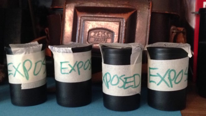
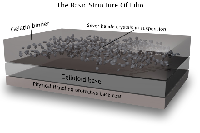
And it is film that will make Luna 3’s mission possible. Enemy film in fact, which the USSR recovered, unexposed, from a CIA spy balloon. Resistant to radiation and extremes of temperature, the 35mm isochromatic stock is chosen by Soviet scientists to be loaded into Luna 3’s AFA-Ye1 camera, part of its Yenisey-2 imaging system.

Luna 3 launches on October 4th, 1959 from Baikonur Cosmodrome in what will one day be Kazakhstan. A modified R-7 rocket inserts the probe into a highly elliptical Earth orbit which, after some over-heating and communications issues are resolved, brings it within range of the moon three days later.

The mission has been timed so that the far side of the moon is in sunlight when Luna 3 reaches it. A pioneering three-axis stabilisation system points the craft (and thus the camera, which cannot pan independently) at the side of the moon which no-one has seen before. A photocell detects the bright surface and triggers the Yenisey-2 system. Alternating between 200mm f/5.6 and 500mm f/9.5 lenses, the camera exposes 29 photographs on the ex-CIA film.

The AFA-Ye1 camera

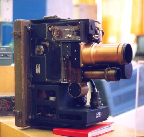
Next that film must be processed, and Luna 3 can’t exactly drop it off at Snappy Snaps. In fact, the Yenisey-2 system contains a fully automated photo lab which develops, fixes and dries the film, all inside a 1.3x1m cylinder tumbling through the vacuum of space at thousands of miles per hour.

Now what? Returning a spacecraft safely to Earth is beyond human ability in 1959, though the following year’s Vostok missions will change all that. Once Luna 3 has swung around the moon and has line of sight to the receiving stations on Earth, the photographic negatives must be converted to radio broadcasts.

To that end, Yenisey-2 incorporates a cathode ray tube which projects a beam of light through the negative, scanning it at a 1,000-line resolution. A photocell on the other side receives the beam, producing a voltage inversely proportional to the density of the negative. This voltage frequency-modulates a radio signal in the same way that fax machines use frequency-modulated audio to send images along phone lines.

Attempts to transmit the photographs begin on October 8th, and after several failures, 17 images are eventually reconstructed by the receiving stations in Crimea and Kamchatka. They are noisy, they are blocky, they are monochromatic, but they show a sight that has been hidden from human eyes since the dawn of time. Featuring many more craters and mountains and many fewer “seas” than the side we’re used to, Luna 3’s pictures prompt a complete rethink of the moon’s history.

Its mission accomplished, the probe spirals in a decaying orbit until it finally burns up in Earth’s atmosphere. In 1961, Yuri Gagarin’s historic flight will capture the public imagination, and unmanned space missions will suddenly seem much less interesting.

But next time you effortlessly WhatsApp a photo to a friend, spare a thought for the remarkable engineering that one day sent never-before-seen photographs across the gulf of space without the aid of digital imaging.

One of the 500mm exposures
Luna 3: Photographing the Far Side of the Moon without Digital Technology

Making a 35mm Zoetrope: The Results

In the early days of lockdown, I blogged about my intentions to build a zoetrope, a Victorian optical device that creates the illusion of a moving image inside a spinning drum. I even provided instructions for building your own, sized like mine to accommodate 18 looping frames of contact-printed 35mm photographs. Well, last week I was finally able to hire my usual darkoom, develop and print the image sequences I had shot over the last five months, and see whether my low-tech motion picture system worked.


Making Mini Movies

Shooting “Sundial”

Before I get to the results, let me say a little about the image sequences themselves and how they were created. Because I was shooting on an SLR, the fastest frame rate I could ever hope to record at was about 1fps, so I was limited to time-lapses or stop motion animation.

Regular readers may recall that the very first sequence I captured was a time-lapse of the cherry tree in my front garden blossoming. I went on to shoot two more time-lapses, shorter-term ones showing sunlight moving across objects during a single day: a circle of rotting apples in a birdbath (which I call Sundial), and a collection of props from my flatmate’s fantasy films (which I call Barrels). I recorded all the time-lapses with the pinhole I made in 2018.

Filming “Social Distance”

The remaining six sequences were all animations, lensed on 28mm, 50mm or 135mm SMC Pentax-Asahi glass. I had no signficant prior experience of this artform, but I certainly had great fun creating some animated responses to the Covid-19 pandemic. My childish raw materials ranged from Blue Peter-esque toilet roll tubes, through Play-Doh to Lego. Orbit features the earth circling a giant Covid-19, and The Sneeze sees a toilet roll person sternutating into their elbow. Happy Birthday shows a pair of rubber glove hands washing themselves, while Avoidance depicts two Lego pedestrians keeping their distance. 360° is a pan of a room in which I am variously sitting, standing and lying as I contemplate lockdown, and finally Social Distance tracks along with a pair of shoes as they walk past coronavirus signage.

The replacement faces for the toilet paper star of “The Sneeze”

By the time I finished shooting all these, I had already learnt a few things about viewing sequences in a zoetrope, by drawing a simple animation of a man walking. Firstly I discovered that the slots in my device – initially 3mm in width – were too large. I therefore retrofitted the drum with 1mm slots, resulting in reduced motion blur but a darker image, much like reducing the shutter angle on a movie camera. I initially made the mistake of putting my eye right up to the drum when viewing the animation, but this destroys the shuttering effect of the slots. Instead the best results seem to be obtained with a viewing distance of about 30cm (1ft).

I could already see where I might have made mistakes with my photographed sequences. The hand-drawn man was bold and simple; it looked best in good light, by a window or outdoors, but it was clear enough to be made out even if the light was a bit poor and there was too much motion blur. Would the same be said of my 35mm sequences?


Postproduction

I contact-printed the nine photographic sequences in the usual way, each one producing three rows of six frames on a single sheet of 8×10″ Ilford MG RC paper. In theory, all that was left was to cut out these rows and glue them together.

In practice, I had managed to screw up a few of the sequences by fogging the start of the film, shooting a frame with bad exposure, or some other act of shameful incompetence. In such cases I had to edit much like filmmakers did before the invention of digital NLEs – by cutting the strips of images, excising the rotten frames and taping them back together. I even printed some of the sequences twice so that I could splice in duplicate frames, where my errors had left a sequence lacking the full 18 images. (This was effectively step-printing, the obsolete optical process by which a shot captured at 24fps could be converted to slow motion by printing each frame twice.)

"Blossom"

Once the sequences were edited, I glued them into loops and could at last view them in the zoetrope. The results were mixed.

Barrels fails because the moving sunlight is too subtle to be discerned through the spinning slots. The same is partly true of Sundial, but the transient glare caused by the sun reflecting off the water at its zenith gives a better sense of motion. Blossom shows movement but I don’t think an uninitiated viewer would know what they were looking at, so small and detailed is the image. Orbit suffers from smallness too, with the earth and Covid-19 unrecognisable. (These last two sequences would have benefitted from colour, undoubtedly.)

The planet Covid-19 (as seen by my phone camera) made from Play-Doh and cloves

I’m very pleased with the animation of Social Distance, though I need to reprint it brighter for it to be truly effective. You can just about make out that there are two people passing each other in Avoidance, but I don’t think it’s at all clear that one is stepping into the road to maintain a safe distance from the other. Happy Birthday is a bit hard to make out too. Similarly, you can tell that 360° is a pan of a room, but that’s about it.

Perhaps the most successful sequence is The Sneeze, with its bold, white toilet roll man against a plain black background.

"Happy Birthday"


Conclusions

Any future zoetrope movies need to be bold, high in contrast and low in detail. I need to take more care to choose colours that read as very different tones when captured in black and white.

Despite the underwhelming results, I had a great time doing this project. It was nice to be doing something hands-on that didn’t involve sitting at a screen, and it’s always good to get more practice at exposing film correctly. I don’t think I’ll ever make an animator though – 18 frames is about the limit of my patience.

My light meter lies beside my animation chart for the walking feet in “Social Distance”.


Making a 35mm Zoetrope: The Results

Making an Analogue Print

This is the latest in my series about analogue photography. Previously, I’ve covered the science behind film capture, and how to develop your own black-and-white film. Now we’ll proceed to the next step: taking your negative and producing a print from it. Along the way we’ll discover the analogue origins of Photoshop’s dodge and burn tools.


Contact printing

35mm contact sheet

To briefly summarise my earlier posts, we’ve seen that photographic emulsion – with the exception of colour slide film – turns black when exposed to light, and remains transparent when not. This is how we end up with a negative, in which dark areas correspond to the highlights in the scene, and light areas correspond with the shadows.

The simplest way to make a positive print from a negative is contact-printing, so called because the negative is placed in direct contact with the photographic printing paper. This is typically done in a spring-loaded contact printing frame, the top of which is made of glass. You shine light through the glass, usually from an enlarger – see below – for a measured period of time, determined by trial and error. Where the negative is dark (highlights) the light can’t get through, and the photographic emulsion on the paper remains transparent, allowing the white paper base to show through. Where the negative is transparent (shadows) the light passes through, and the emulsion – once developed and fixed in the same way as the original film – turns black. Thus a positive image is produced.

Normally you would contact-print multiple strips of negative at the same time, perhaps an entire roll of film’s worth, if your paper is large enough to fit them all. Then you can examine them through a loupe to decide which ones are worth enlarging. You have probably seen contact sheets, complete with circled images, stars and arrows indicating which frames the photographer or picture editor likes, where they might crop it, and which areas need doctoring. In fact, contact sheets are so aesthetically pleasing that it’s not uncommon these days for graphic designers to create fake digital ones.

The correct exposure time for a contact print can be found by exposing the whole sheet for, say, ten seconds, then covering a third of it with a piece of card, exposing it for another ten seconds, then covering that same third plus another third and exposing it for ten seconds more. Once developed, you can decide which exposure you like best, or try another set of timings.

120 contact sheet


Making an enlargement

Contact prints are all well and good, but they’re always the same size as the camera negative, which usually isn’t big enough for a finished product, especially with 35mm. This is where an enlarger comes in.

An enlarger is essentially a projector mounted on a stand. You place the negative of your chosen image into a drawer called the negative carrier. Above this is a bulb, and below it is a lens. When the bulb is turned on, light shines through the negative, and the lens focuses the image (upside-down of course) onto the paper below. By adjusting the height of the enlarger’s stand, you can alter the size of the projected image.

Just like a camera lens, an enlarger’s lens has adjustable focus and aperture. You can scrutinise the projected image using a loupe; if you can see the grain of the film, you know that the image is sharply focused.

The aperture is marked in f-stops as you would expect, and just like when shooting, you can trade off the iris size against the exposure time. For example, a print exposed for 30 seconds at f/8 will have the same brightness as one exposed for 15 seconds at f/5.6. (Opening from f/8 to f/5.6 doubles the light, or increases exposure by one stop, while halving the time cuts the light back to its original value.)


Dodging and burning

As with contact-printing, the optimum exposure for an enlargement can be found by test-printing strips for different lengths of time. This brings us to dodging and burning, which are respectively methods of decreasing or increasing the exposure time of specific parts of the image.

Remember that the printing paper starts off bright white, and turns black with exposure, so to brighten part of the image you need to reduce its exposure. This can be achieved by placing anything opaque between the projector lens and the paper for part of the exposure time. Typically a circle of cardboard on a piece of wire is used; this is known as a dodger. That’s the “lollipop” you see in the Photoshop icon. It’s important to keep the dodger moving during the exposure, otherwise you’ll end up with a sharply-defined bright area (not to mention a visible line where the wire handle was) rather than something subtle.

I dodged the robin in this image, to help him stand out.

Let me just say that dodging is a joyful thing to do. It’s such a primitive-looking tool, but you feel like a child with a magic wand when you’re using it, and it can improve an image no end. It’s common practice today for digital colourists to power-window a face and increase its luminance to draw the eye to it; photographers have been doing this for decades and decades.

Burning is of couse the opposite of dodging, i.e. increasing the exposure time of part of the picture to make it darker. One common application is to bring back detail in a bright sky. To do this you would first of all expose the entire image in such a way that the land will look good. Then, before developing, you would use a piece of card to cover the land, and expose the sky for maybe five or ten seconds more. Again, you would keep the card in constant motion to blend the edges of the effect.

To burn a smaller area, you would cut a hole in a piece of card, or simply form your hands into a rough hole, as depicted in the Photoshop icon.


Requirements of a darkroom

The crucial thing which I haven’t yet mentioned is that all of the above needs to take place in near-darkness. Black-and-white photographic paper is less sensitive to the red end of the spectrum, so a dim red lamp known as a safe-light can be used to see what you’re doing. Anything brighter – even your phone’s screen – will fog your photographic paper as soon as you take it out of its lightproof box.

Once your print is exposed, you need to agitate it in a tray of diluted developer for a couple of minutes, then dip it in a tray of water, then place it in a tray of diluted fixer. Only then can you turn on the main lights, but you must still fix the image for five minutes, then leave it in running water for ten minutes before drying it. (This all assumes you’re using resin-coated paper.)

Because you need an enlarger, which is fairly bulky, and space for the trays of chemicals, and running water, all in a room that is one hundred per cent lightproof, printing is a difficult thing to do at home. Fortunately there are a number of darkrooms available for hire around the country, so why not search for a local one and give analogue printing a go?

Some enlargements from 35mm on 8×10″ paper


Making an Analogue Print

How to Process Black-and-White Film

A few weeks ago, I came very close to investing in an Ilford/Paterson Starter Kit so that I could process film at home. I have four exposed rolls of 35mm HP5+ sitting on my shelf, and I thought that developing them at home might be a nice way to kill a bit of lockdown time. However, I still wouldn’t be able to print them, due to the difficulties of creating a darkroom in my flat. And with lockdown now easing, it probably won’t be long until I can get to Holborn Studios and hire their darkroom as usual.

So in this article I’ll talk through the process of developing a roll of black-and-white 35mm, as I would do it in the Holborn darkoom. If you haven’t already, you might want to read my post about how film works first.


You will need


Loading the developing tank

Holborn Studios’ darkroom, run by Bill Ling, displays this handy reminder.

The first step is to transfer the exposed film from its cassette – which is of course light-proof – into the Paterson tank, which is designed to admit the developing chemicals but not light. This transfer must take place in complete darkness, to avoid fogging the film. I’ve always done this using a changing bag, which is a black bag with a double seal and elasticated arm-holes.

Start by putting the following items into the bag: the film cassette, scissors and the various components of the Paterson tank, including the spiral. It’s wise to put in an empty film canister too, in case something goes wrong, and if the tail of your film isn’t sticking out of the cassette then you’ll need a can opener as well.

Seal the bag, put your arms in, and pull all the film out of the cassette. It’s important NOT to remove your arms from the bag now, until the film is safely inside the closed tank, otherwise light can get in through the arm-holes and fog the film.

Use the scissors to cut the end of the film from the cassette, and to trim the tongue (narrower part) off the head of the film.

Paterson Universal Developing Tank components, clockwise from the white items: developing reels or spirals, tank, light-proof lid, waterproof cap, and agitator – which I never use. In the centre is the core.

Now we come to the most difficult part, the part which always has me sweating and swearing and regretting all my life choices: loading the film onto the spiral. I have practised this with dead film many times, but when I’m fumbling around in the dark of the changing bag it’s a hundred times harder.

It’s hard to describe loading the spiral verbally, but this blog post by Chris Waller is very clear and even includes pictures. (Chris recommends cutting a slight chamfer onto the leading corners of the film, which I shall certainly try next time, as well as using your thumbs to keep the film flat on its approach to the reel.)

If you’re working with 120 film, the loading process is very slightly different, and this video describes it well.

Once the spiral is loaded, you can thread it onto the core, place the core inside the tank, and then put the lid on. It is now safe to open the bag.


Developing

Developing time info displayed at Holborn Studios

Holborn Studios’ darkroom is stocked with a working solution of Kodak HC-110 developer, but if you don’t have this luxury, or you’re not using the Ilford Simplicity packs, then you’ll need to make up a working solution yourself by diluting the developer according to the manufacturer’s instructions. For HC-110 dilution B, which is what Holborn uses, it’s 1+31, i.e.one part concentrated developer to 31 parts water. The working solution has a limited shelf life, so again consult the manufacturer’s instructions.

Further dilution is required at the point of development, at a ratio of 1+7 in this case, but once more this may vary depending on the chemicals you choose. For one roll of 35mm, you need 37.5ml of the HC-110 dilution B, and 262.5ml of water for a total of 300ml.

The developing time depends on the type of film stock, the speed you rated it at, the type of developer and its dilution, and the temperature of the chemicals. Digital Truth has all the figures you need to find the right development time.

Agitating

I was taught to ensure my water is always at 20°C before mixing it with the developer, to keep the timing calculations a little simpler. At this temperature, a roll of Ilford HP5+ rated at its box speed of ISO 400 needs five minutes to develop in HC-110 dilution B. Ilford Delta, on the other hand, needs a whopping 14.5 minutes to process at its box speed of 3200.

Once your diluted developer is ready, pour it into the Paterson tank and put on the cap. It is now necessary to agitate the chemicals in order to distribute them evenly around the film. My technique is inversion, i.e. turning the tank upside-down and back again. Do this continuously for the first 30 seconds, then for 10 seconds every minute after that.

Inside the tank, your latent image is being transformed into an image proper, wherein every exposed silver halide crystal is now black metallic silver.


Fixing

Once the developing time is up, remove the cap from the tank, and pour away the developer immediately. At this point some people will say you need to use a stop bath to put a firm halt to the developing process, but I was taught simply to rinse the tank out with tap water and then proceed straight to fixing. This method has always worked fine for me.

After rinsing the tank, pour in enough fix solution (again prepared to the manufacturer’s instructions) to fill it completely. Put the cap back on, agitate it for 30 seconds, then leave it for ten minutes.

During this time, the fixer renders the film’s unexposed crystals inactive and water soluble. When the ten minutes is up, pour the fixer back into its container (it’s reuseable) and leave the tank under running water for a further ten minutes. This washes away the unused silver halide crystals, leaving only the exposed black silver corresponding with light areas of the scene, and just the transparent plastic base corresponding with the dark areas.

Squirt a little diluted washing-up liquid into the tank to prevent drying rings, then drain it. You can now open the tank and see your negative for the first time.


Drying

Remove the film from the developing spiral, taking care to only touch the ends and the edges. Squeegee the top part of the film, dry your hands, then squeegee the rest. This removes droplets which can otherwise mark the negative.

Now attach two hooks to the film, a light one at the top to hang it from, and a heavy one at the bottom to stop the film curling as it dries. Holborn Studios is equipped with a heated drying cabinet, but with patience you can hang a film to dry in any dust-free area.

When your film is dry, you can cut it into strips of six frames and insert them into a negative storage sheet.

You can now scan your negatives, or better still print them photo-chemically, as I’ll describe in a future post.

How to Process Black-and-White Film

How Film Works

Over the ten weeks of lockdown to date, I have accumulated four rolls of 35mm film to process. They may have to wait until it is safe for me to visit my usual darkroom in London, unless I decide to invest in the equipment to process film here at home. As this is something I’ve been seriously considering, I thought this would be a good time to remind myself of the science behind it all, by describing how film and the negative process work.


Black and White

The first thing to understand is that the terminology is full of lies. There is no celluloid involved in film – at least not any more – and there never has been any emulsion.

However, the word “film” itself is at least accurate; it is quite literally a strip of plastic backing coated with a film of chemicals, even if that plastic is not celluloid and those chemicals are not an emulsion. Celluloid (cellulose mononitrate) was phased out in the mid-twentieth century due to its rampant inflammability, and a variety of other flexible plastics have been used since.

As for “emulsion”, it is in fact a suspension of silver halide crystals in gelatine. The bigger the crystals, the grainier the film, but the more light-sensitive too. When the crystals are exposed to light, tiny specks of metallic silver are formed. This is known as the latent image. Even if we could somehow view the film at this stage without fogging it completely, we would see no visible image as yet.

For that we need to process the film, by bathing it in a chemical developer. Any sufficiently large specks of silver will react with the developer to turn the entire silver halide crystal into black metallic silver. Thus areas that were exposed to light turn black, while unlit areas remain transparent; we now have a negative image.

Before we can examine the negative, however, we must use a fixer to turn the unexposed silver halide crystals into a light-insensitive, water-soluble compound that we can wash away.

Now we can dry our negative. At this stage it can be scanned for digital manipulation, or printed photo-chemically. This latter process involves shining light through the negative onto a sheet of paper coated with more photographic emulsion, then processing and fixing that paper as with the film. (As the paper’s emulsion is not sensitive to the full spectrum of light, this procedure can be carried out under dim red illumination from a safe-light.) Crystals on the paper turn black when exposed to light – as they are through the transparent portions of the negative, which you will recall correspond to the shadows of the image – while unexposed crystals again remain transparent, allowing the white of the paper to show through. Thus the negative is inverted and a positive image results.


Colour

Things are a little more complicated with colour, as you might expect. I’ve never processed colour film myself, and I currently have no intention of trying!

The main difference is that the film itself contains multiple layers of emulsion, each sensitive to different parts of the spectrum, and separated by colour filters. When the film is developed, the by-products of the chemical reaction combine with colour couplers to create colour dyes.

An additional processing step is introduced between the development and the fixing: the bleach step. This converts the silver back to silver halide crystals which are then removed during fixing. The colour dyes remain, and it is these that form the image.

Many cinematographers will have heard of a process call bleach bypass, used on such movies as 1984 and Saving Private Ryan. You can probably guess now that this process means skipping or reducing the bleach step, so as to leave the metallic silver in the negative. We’ve seen that this metallic silver forms the entire image in black-and-white photography, so by leaving it in a colour negative you are effectively combining colour and black-and-white images in the same frame, resulting in low colour saturation and increased contrast.

“1984” (DP: Roger Deakins CBE, ASC, BSC)

Colour printing paper also contains colour couplers and is processed again with a bleach step. Because of its spectral sensitivity, colour papers must be printed and processed in complete darkness or under a very weak amber light.


Coming Up

In future posts I will cover the black-and-white processing and printing process from a much more practical standpoint, guiding you through it, step by step. I will also look at the creative possibilities of the enlargement process, and we’ll discover where the Photoshop “dodge” and “burn” tools had their origins. For those of you who aren’t Luddites, I’ll delve into how digital sensors capture and process images too!

How Film Works

How Analogue Photography Can Make You a Better Cinematographer

With many of us looking for new hobbies to see us through the zombie apocalypse Covid-19 lockdown, analogue photography may be the perfect one for an out-of-work DP. While few of us may get to experience the magic and discipline of shooting motion picture film, stills film is accessible to all. With a range of stocks on the market, bargain second-hand cameras on eBay, seemingly no end of vintage glass, and even home starter kits for processing your own images, there’s nothing to stop you giving it a go.

Since taking them up again In 2018, I’ve found that 35mm and 120 photography have had a positive impact on my digital cinematography. Here are five ways in which I think celluloid photography can help you too sharpen your filmmaking skills.


1. Thinking before you click

When you only have 36 shots on your roll and that roll cost you money, you suddenly have a different attitude to clicking the shutter. Is this image worthy of a place amongst those 36? If you’re shooting medium or large-format then the effect is multiplied. In fact, given that we all carry phone cameras with us everywhere we go, there has to be a pretty compelling reason to lug an SLR or view camera around. That’s bound to raise your game, making you think longer and harder about composition and content, to make every frame of celluloid a minor work of art.


2. Judging exposure

I know a gaffer who can step outside and tell you what f-stop the light is, using only his naked eye. This is largely because he is a keen analogue photographer. You can expose film by relying on your camera’s built-in TTL (through the lens) meter, but since you can’t see the results until the film is processed, analogue photographers tend to use other methods as well, or instead, to ensure a well-exposed negative. Rules like “Sunny Sixteen” (on a sunny day, set the aperture to f/16 and the shutter speed reciprocal to match the ISO, e.g. 1/200th of a second at ISO 200) and the use of handheld incident meters make you more aware of the light levels around you. A DP with this experience can get their lighting right more quickly.


3. Pre-visualising results

We digital DPs can fall into the habit of not looking at things with our eyes, always going straight to the viewfinder or the monitor to judge how things look. Since the optical viewfinder of an analogue camera tells you little more than the framing, you tend to spend less time looking through the camera and more using your eye and your mind to visualise how the image will look. This is especially true when it comes to white balance, exposure and the distribution of tones across a finished print, none of which are revealed by an analogue viewfinder. Exercising your mind like this gives you better intuition and increases your ability to plan a shoot, through storyboarding, for example.


4. Grading

If you take your analogue ethic through to post production by processing and printing your own photographs, there is even more to learn. Although detailed manipulation of motion pictures in post is relatively new, people have been doctoring still photos pretty much since the birth of the medium in the mid-19th century. Discovering the low-tech origins of Photoshop’s dodge and burn tools to adjust highlights and shadows is a pure joy, like waving a magic wand over your prints. More importantly, although the printing process is quick, it’s not instantaneous like Resolve or Baselight, so you do need to look carefully at your print, visualise the changes you’d like to make, and then execute them. As a DP, this makes you more critical of your own work and as a colourist, it enables you to work more efficiently by quickly identifying how a shot can be improved.


5. Understanding

Finally, working with the medium which digital was designed to imitate gives you a better understanding of that imitation. It was only when I learnt about push- and pull-processing – varying the development time of a film to alter the brightness of the final image – that my understanding of digital ISO really clicked. Indeed, some argue that electronic cameras don’t really have ISO, that it’s just a simulation to help users from an analogue background to understand what’s going on. If all you’ve ever used is the simulation (digital), then you’re unlikely to grasp the concepts in the same way that you would if you’ve tried the original (analogue).

How Analogue Photography Can Make You a Better Cinematographer

Pinhole Results

In my last couple of posts I described making and shooting with a pinhole attachment for my 35mm Pentax P30t SLR. Well, the scans are now back from the lab and I’m very pleased with them. They were shot on Fujifilm Superia Xtra 400.

As suspected, the 0.7mm pinhole was far too big, and the results are super-blurry:

See how contemptuous Spike is of this image. Or maybe that’s just Resting Cat Face.

The 0.125mm hole produced much better results, as you can see below. My f/stop calculations (f/365) seem to have been pretty close to the mark, although, as is often the case with film, the occasions where I gave it an extra stop of exposure produced even richer images. Exposure times for these varied between 2 and 16 seconds. Click to see them at higher resolution.

I love the ethereal, haunting quality of all these pictures, which recalls the fragility of Victorian photographs. It’s given me several ideas for new photography projects…

SaveSave

Pinhole Results

Adventures with a Pinhole

Last week I discussed making a pinhole for my Pentax 35mm SLR. Since then I’ve made a second pinhole and shot a roll of Fujifilm Superia X-tra 400 with them. Although I haven’t had the film processed yet, so the quality of the images is still a mystery, I’ve found shooting with a pinhole to be a really useful exercise.

My Pentax P30T fitted with a 0.125mm pinhole attachment


A Smaller Pinhole

Soon after my previous post, I went out into the back garden and took ten exposures of the pond and the neighbour’s cat with the 0.7mm pinhole. By that point I had decided that the hole was almost certainly too big. As I noted last week, Mr Pinhole gives an optimal diameter of 0.284mm for my camera. Besides that, the (incredibly dark) images in my viewfinder were very blurry, a sign that the hole needed to be smaller.

Scans of my two pinholes

So I peeled the piece of black wrap with the 0.7mm pinhole off my drilled body cap and replaced it with another hole measuring about 0.125mm. I had actually made this smaller hole first but rejected it because absolutely nothing was visible through the viewfinder, except for a bit of a blur in the centre. But now I came to accept that I would have to shoot blind if I wanted my images to be anything approaching sharp.

The 0.125mm(ish) pinhole magnified in Photoshop

I had made the 0.125mm hole by tapping the black wrap with only the very tip of the needle, rather than pushing it fully through. Prior to taping it into the body cap, I scanned it at high resolution and measured it using Photoshop. This revealed that it’s a very irregular shape, which probably means the images will still be pretty soft. Unfortunately I couldn’t see a way of getting it any more circular; sanding didn’t seem to help.

Again I found the f-stop of the pinhole by dividing the flange focal distance (45.65mm) by the hole diameter, the result being about f/365. My incident-light meter only goes up to f/90, so I needed to figure out how many stops away from f/365 that is. I’m used to working in the f/1.4-f/22 range, so I wasn’t familiar with how the stop series progresses above f/90. Turns out that you can just multiply by 1.4 to roughly find the next stop up, so after f/90 it’s 128, then 180, then 256, then 358, pretty close to my f/365 pinhole. So whatever reading my meter gave me for f/90, I knew that I would need to add 4 stops of exposure, i.e. multiply the shutter interval by 16. (Stops are a base 2 logarithmic scale. See my article on f-stops, T-stops and ND filters for more info.)


The Freedom of Pinhole Shooting

I’ve just spent a pleasant hour or so in the garden shooting the remaining 26 exposures on my roll with the new 0.125mm pinhole. Regardless of how the photos come out, I found it a fun and fascinating exercise.

Knowing that the images would be soft made me concentrate on colour and form far more than I normally would. Not being able to frame using the viewfinder forced me to visualise the composition mentally. And as someone who finds traditional SLRs very tricky to focus, it was incredibly freeing not to have to worry about that, not to have to squint through the viewfinder at all, but just plonk the camera down where it looked right and squeeze the shutter.

Of course, before squeezing the shutter I needed to take incident-light readings, because the TTL (through the lens) meter was doing nothing but flash “underexposed” at me. Being able to rely solely on an incident meter to judge exposure is a very useful skill for a DP, so this was great practice. I’ve been reading a lot about Ansel Adams and the Zone System lately, and although this requires a spot reflectance meter to be implemented properly, I tried to follow Adams’ philosophy, visualising how I wanted the subject’s tones to correspond to the eventual print tones. (Expect an article about the Zone System in the not-too-distant future!)


D.I.Y. pinhole Camera

On Tuesday night I went along to a meeting of Cambridge Darkroom, the local camera club. By coincidence, this month’s subject was pinhole cameras. Using online plans, Rich Etteridge had made up kits for us to construct our own complete pinhole cameras in groups. I teamed up with a philosophy student called Tim, and we glued a contraption together in the finest Blue Peter style. The actual pinholes were made in metal squares cut from Foster’s cans, which are apparently something Rich has in abundance.

DIY pinhole camera

I have to be honest though: I’m quite scared of trying to use it. Look at those dowels. Can I really see any outcome of attempting to load this camera other than a heap of fogged film on the floor? No. I think I’ll stick with my actual professionally-made camera body for now. If the pinhole photos I took with that come out alright, then maaaaaaybe I’ll consider lowering the tech level further and trying out my Blue Peter camera. Either way, big thanks to Rich for taking all that time to produce the kits and talk us through the construction.

Watch this space to find out how my pinhole images come out.

SaveSave

Adventures with a Pinhole

Making a Pinhole Attachment for an SLR

Last autumn, after a few years away from it, I got back into 35mm stills photography. I’ve been reading a lot of books about photography: the art of it, the science and the history too. I’ve even taken a darkroom course to learn how to process and print my own black and white photos.

Shooting stills in my spare time gives me more opportunities to develop my eye for composition, my exposure-judging skills and my appreciation of natural light. Beyond that, I’ve discovered interesting parallels between electronic and photochemical imaging which enhance my understanding of both.

For example, I used to think of changing the ISO on a digital camera as analogous to loading a different film stock into a traditional camera. However, I’ve come to realise it’s more like changing the development time – it’s an after-the-fact adjustment to an already-captured (latent) image. There’s more detail on this analogy in my ISO article at Red Shark News.

The importance of rating an entire roll of film at the same exposure index, as it must all be developed for the same length of time, also has resonance in the digital world. Maintaining a consistency of exposure (or the same LUT) throughout a scene or sequence is important in digital filmmaking because it makes the dailies more watchable and reduces the amount of micro-correction which the colourist has to do down the line.

Anyway, this is all a roundabout way of explaining why I decided to make a pinhole attachment for my SLR this week. It’s partly curiosity, partly to increase my understanding of image-making from first principles.

The pinhole camera is the simplest image-making device possible. Because light rays travel in straight lines, when they pass through a very small hole they emerge from the opposite side in exactly the same arrangement, only upside-down, and thus form an image on a flat surface on the other side. Make that flat surface a sheet of film or a digital sensor and you can capture this image.


How to make a pinhole attachment

I used Experimental Filmmaking: Break the Machine by Kathryn Ramey as my guide, but it’s really pretty straightforward.

You will need:

  • an extra body cap for your camera,
  • a drill,
  • a small piece of smooth, non-crumpled black wrap, or kitchen foil painted black,
  • scissors,
  • gaffer tape (of course), and
  • a needle or pin.

Instructions:

  1. Drill a hole in the centre of the body cap. The size of the hole is unimportant.
  2. Use the pin or needle to pierce a hole in the black wrap, at least a couple of centimetres from the edge.
  3. Cut out a rough circle of the black wrap, with the pinhole in the middle. This circle needs to fit on the inside of the body cap, with the pinhole in the centre of the drilled hole.
  4. Use the gaffer tape to fix the black wrap tightly to the inside of the body cap.
  5. Fit the body cap to your camera.

The smaller the pinhole is, the sharper the image will be, but the darker too. The first pinhole I made was about 0.1-0.2mm in diameter, but when I fitted it to my camera and looked through the viewfinder I could hardly make anything out at all. So I made a second one, this time pushing the pin properly through the black wrap, rather than just pricking it with the tip. (Minds out of the gutter, please.) The new hole was about 0.7mm but still produced an incredibly dark image in the viewfinder.


Exposing a pinhole image

If you’re using a digital camera, you can of course judge your exposure off the live-view screen. Things are a little more complicated if, like me, you’re shooting on film.

In theory the TTL (through the lens) light meter should give me just as reliable a reading as it would with a lens. The problem is that, even with the shutter set to 1 second, and ISO 400 Fujifilm Super X-tra loaded, the meter tells me I’m underexposed. Admittedly the weather has been overcast since I made the pinhole yesterday, so I may get a useful reading when the sun decides to come out again.

Failing that, I can use my handheld incident-light meter to determine the exposure…. once I’ve worked out what the f-stop of my pinhole is.

As I described in my article on aperture settings, the definition of an f-stop is: the ratio of the focal length to the aperture diameter. We’re all used to using lenses that have a clearly defined and marked focal length, but what is the focal length in a pinhole system?

The definition of focal length is the distance between the point where the light rays focus (i.e. converge to a point) and the image plane. So the focal length of a pinhole camera is very simply the distance from the pinhole itself to the film or digital sensor. Since my pinhole is more or less level with the top of the lens mount, the focal length is going to be approximately equal to the camera’s flange focal distance (defined as the distance between the lens mount and the image plane). According to Wikipedia, the flange focal distance for a Pentax K-mount camera is 45.46mm.

So the f-stop of my 0.7mm pinhole is f/64, because 45.64 ÷ 0.7 ≈ 64. Conveniently, f/64 is the highest stop my light meter will handle.

The website Mr Pinhole has a calculator to help you figure this sort of stuff out, and it even tells you the optimal pinhole diameter for your focal length. Apparently this is 0.284mm in my case, so my images are likely to be quite soft.

Anyway, when the sun comes out I’ll take some pictures and let you know how I get on!

Making a Pinhole Attachment for an SLR

The Normal Lens

Today I’m investigating the so-called normal (a.k.a. standard) lens, finding out exactly what it is, the history behind it, and how it’s relevant to contemporary cinematographers.


The Normal lens in still photography

A normal lens is one whose focal length is equal to the measurement across the diagonal of the recorded image. This gives an angle of view of about 53°, which is roughly equivalent to that of the human eye, at least the angle within which the eye can see detail. If a photo taken with a normal lens is printed and held up in front of the real scene, with the distance from the observer to the print being equal to the diagonal of the print, then objects in the photo will look exactly the same size as the real objects.

Asahi Pentax-M 50mm/f1.4 – a normal lens for 35mm stills

Lenses with a shorter focal length than the normal are known as wide-angle. Lenses with a greater focal length than the normal are considered to be long lenses. (Sometimes you will hear the term telephoto used interchangeably with long lens, but a telephoto lens is technically one which has a focal length greater than its physical length.)

A still 35mm negative is 43.3mm across the diagonal, but this got rounded up quite a bit — by Leica inventor Oskar Barnack — so that 50mm is widely considered to be the normal lens in the photography world. Indeed, some photographers rarely stray from the 50mm. For some this is simply because of its convenience; it is the easiest length of lens to manufacture, and therefore the cheapest and lightest. Because it’s neither too short nor too long, all types of compositions can be achieved with it. Other photographers are more dogmatic, considering a normal lens the only authentic way to capture an image, believing that any other length falsifies or distorts perspective.


The normal lens in cinematography

SMPTE (the Society of Motion Picture and Television Engineers), or indeed SMPE as it was back then, decided almost a century ago that a normal lens for motion pictures should be one with a focal length equal to twice the image diagonal. They reasoned that this would give a natural field of view to a cinema-goer sitting in the middle of the auditorium, halfway between screen and projector (the latter conventionally fitted with a lens twice the length of the camera’s normal lens).

A Super-35 digital cinema sensor – in common with 35mm motion picture film – has a diagonal of about 28mm. According to SMPE, this gives us a normal focal length of 56mm. Acclaimed twentieth century directors like Hitchcock, Robert Bresson and Yasujiro Ozu were proponents of roughly this focal length, 50mm to be more precise, believing it to have the most natural field of view.

Of course, the 1920s SMPE committee, living in a world where films were only screened in cinemas, could never have predicted the myriad devices on which movies are watched today. Right now I’m viewing my computer monitor from a distance about equal to the diagonal of the screen, but to hold my phone at the distance of its diagonal would make it uncomfortably close to my face. Large movie screens are still closer to most of the audience than their diagonal measurement, just as they were in the twenties, but smaller multiplex screens may be further away than their diagonals, and TV screens vary wildly in size and viewing distance.


The new normal

To land in the middle of the various viewing distances common today, I would argue that filmmakers should revert to the photography standard of a normal focal length equal to the diagonal, so 28mm for a Super-35 sensor.

Deleted scene from “Ren: The Girl with the Mark” shot on a vintage 28mm Pentax-M

According to Noam Kroll, “Spielberg, Scorsese, Orson Wells, Malick, and many other A-list directors have cited the 28mm lens as one of their most frequently used and in some cases a favorite [sic]”.

I have certainly found lenses around that length to be the most useful on set.  A 32mm is often my first choice for handheld, Steadicam, or anything approaching a POV. It’s great for wides because it compresses things a little and crops out unnecessary information while still taking plenty of the scene in. It’s also good for mids and medium close-ups, making the viewer feel involved in the conversation.

When I had to commit to a single prime lens to seal up in a splash housing for a critical ocean scene in The Little Mermaid, I quickly chose a 32mm, knowing that I could get wides and tights just by repositioning myself.

A scene from “The Little Mermaid” which I shot on a 32mm Cooke S4

I’ve found a 32mm useful in situations where coverage was limited. Many scenes in Above the Clouds were captured as a simple shot-reverse: both mids, both on the 32mm. This was done partly to save time, partly because most of the sets were cramped, and partly because it was a very effective way to get close to the characters without losing the body language, which was essential for the comedy. We basically combined the virtues of wides and close-ups into a single shot size!

In addition to the normal lens’ own virtues, I believe that it serves as a useful marker post between wide lenses and long lenses. In the same way that an editor should have a reason to cut, in a perfect world a cinematographer should have a reason to deviate from the normal lens. Choose a lens shorter than the normal and you are deliberately choosing to expand the space, to make things grander, to enhance perspective and push planes apart. Select a lens longer than the normal and you’re opting for portraiture, compression, stylisation, maybe even claustrophobia. Thinking about all this consciously and consistently throughout a production can add immeasurably to the impact of the story.

The Normal Lens