What’s in a DP’s Set Bag?

I used to own a whole bunch of equipment – camera, lenses, lights – but for reasons I’ve detailed elsewhere I got rid of all that back in 2017. These days I travel pretty light (no pun intended) to set, but there are a few items I wouldn’t like to be without.

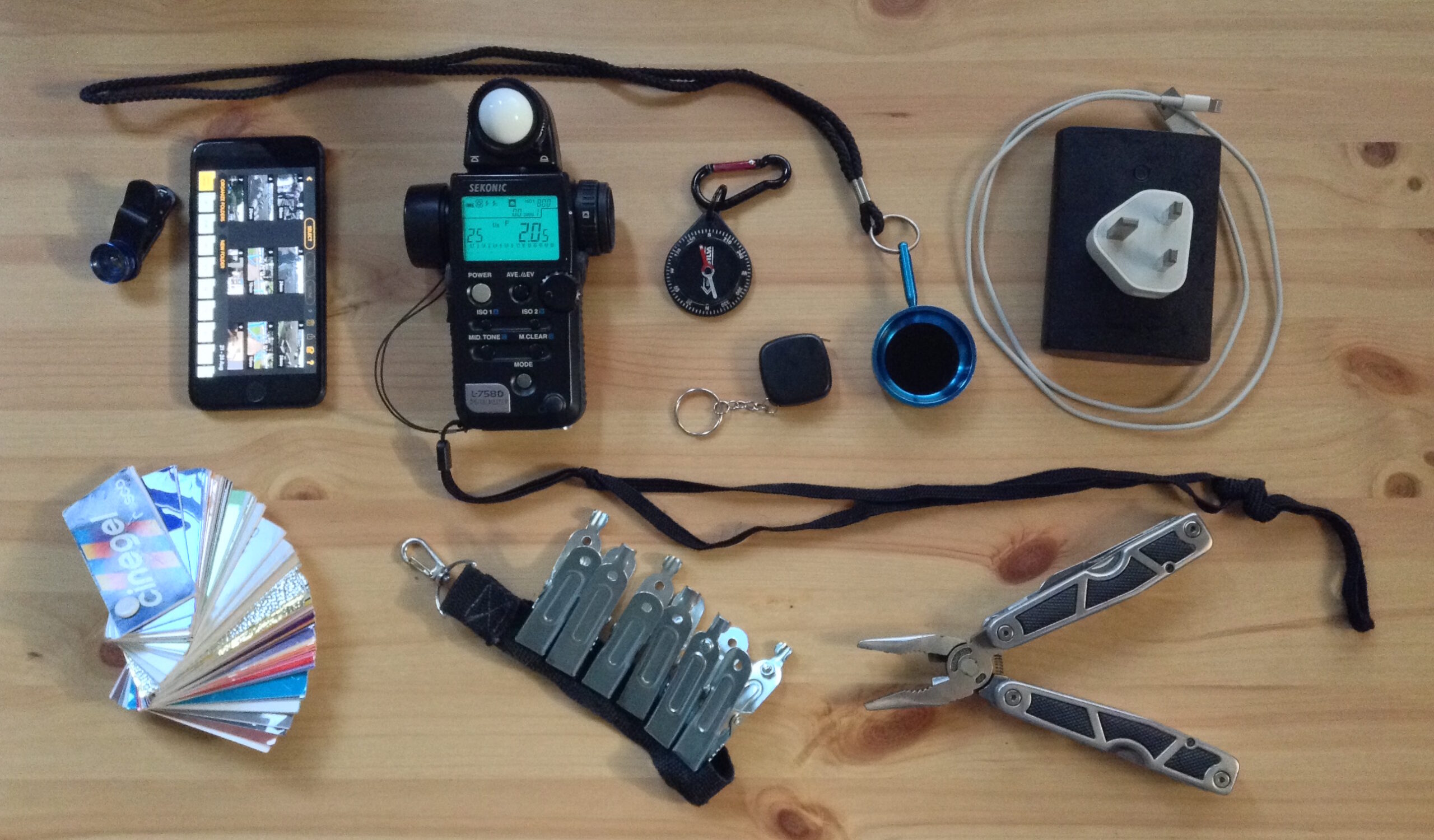
Here’s what’s in my set bag, roughly in descending order of importance.


1. Phone

Alright, this isn’t technically in my set bag, but it is the most used thing on a typical day on set. I use Chemical Wedding‘s Artemis Pro app all the time to find frames and select lenses, the same company’s Helios Pro to look at sun paths, and occasionally other specialist apps like Arri Photometrics (to work out if a particular light is powerful enough at a particular distance) and Flicker Finder (to check if a light will flicker on camera). I’ve also got Lux Calc installed but so far I’ve never used it.

Other common uses of my phone are looking at call sheets and other production documents if hardcopies aren’t supplied, checking my Google Sheets breakdown to remind myself of my creative intentions for the scene, and taking photos of lighting set-ups in case I need to recreate them for pick-ups.

To enable Artemis Pro to simulate wider lenses with my iPhone 7’s relatively tight built-in lens I also carry a clip-on 0.67x wide angle adaptor.


2. Light Meter

I’ve written before about why light meters are still important. My Sekonic L-758D gets heavy use on set, mostly in incident mode but sometimes the spot reflectance mode too; see my post on judging exposure to learn about what these modes do.

I make sure to carry spare batteries for it too.
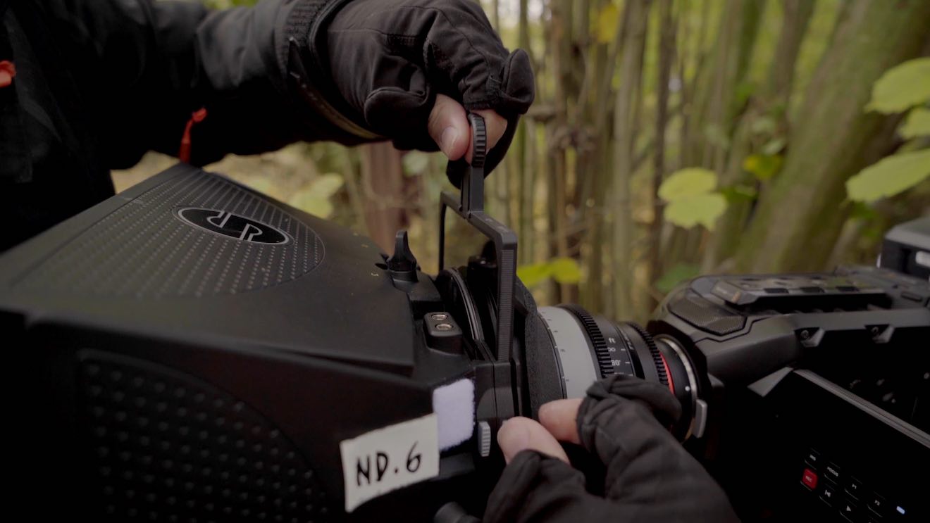
 

3. Gaffer’s Glass

On The Little Mermaid the crew took pity on me using a broken ND filter wrapped in ND gel as a gaffer’s glass and bought me a proper one. This is like a monocle with an ND 3.6 filter in it for looking into fresnels and other directional fixtures to see if the spot of light is aimed exactly where it should be. I mostly use mine to look at the clouds and see when the sun is going to go in and come out, but you shouldn’t use one to look at the naked sun because even with all the ND it can still damage your eyes.


4. Power bank

With the heavy use my phone gets on set the charge doesn’t always last the whole day, so a power bank is essential to keep it running, as of course is the mains charger just in case.


5. Travel mug/flask

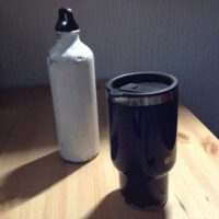
Most productions are environmentally conscious enough now to dissuade people from using disposable coffee cups and water bottes (though there are still a million half-finished water bottles on set at the end of the day). I always bring my own travel mug and metal water bottle. Keeping the mug clean(ish), especially when switching between tea and coffee consumption, is a daily struggle.


6. Croc clips

I always keep a couple of croc clips on my belt when shooting. Although I rarely gel lights myself on larger productions, I find them useful for adjusting curtains to admit just the right amount of daylight, or attaching a rain cover or light-blocking cloth to the camera, or clipping my jacket to something as a last-minute lighting flag.


7. Multi-tool

On some productions I’ve worn a multi-tool on my belt every day and only used it once or twice (usually to open wrap beers), so now it stays in my bag unless it’s specifically needed. As a head of department I theoretically shouldn’t be doing any tasks that would require a multi-tool, but it’s annoying to need one and not have one.


8. Tape Measure

I think my mum gave me this tiny tape measure which I keep in my set bag because it’s so small and light there’s no reason not to. I’ve used it exactly once so far: to work out if an Alexa Classic with a Cooke 10:1 zoom on would fit into certain tight locations on Hamlet.


9. Gel swatches

I picked up a set of Rosco filter swatches at either the BSC Expo or the Media Production Show. I don’t think I’ve ever used it.


10. Compass

Occasionally Helios Pro isn’t playing ball and I need to work out roughly where the sun is going to be, so out comes the traditional compass.


One final thing. Until very recently I carried a pair of gardening gloves for handling hot lights, but again I shouldn’t really be doing this myself and incandescent lamps aren’t too common on sets any more anyway, so when my gloves became worn out enough to need replacing I decided not to bother.

What’s in a DP’s Set Bag?

Exposure Part 2: Neutral Density (ND) Filters

In the first part of this series, I explained the concepts of f-stops and T-stops, and looked at how aperture can be used to control exposure. We saw that changing the aperture causes side effects, most noticeably altering the depth of field.

How can we set the correct exposure without compromising our depth of field? Well, as we’ll see later in this series, we can adjust the shutter angle and/or ISO, but both of those have their own side effects. More commonly a DP will use neutral density (ND) filters to control the amount of light reaching the lens. These filters get their name from the fact that they block all wavelengths of light equally, so they darken the image without affecting the colour.


When to use an ND Filter

Let’s look at an example. Imagine that I want to shoot at T4; this aperture gives a nice depth of field, on the shallow side but not excessively so. My subject is very close to a bright window and my incident light meter is giving me a reading of f/11. (Although I’m aiming for a T-stop rather an f-stop, I can still use the f-number my meter gives me; in fact if my lens were marked in f-stops then my exposure would be slightly off because the meter does not know the transmission efficiency of my lens.) Let’s remind ourselves of the f-stop/T-stop series before we go any further:

1      1.4      2      2.8      4      5.6      8      11      16      22     32

By looking at this series, which can be found printed on any lens barrel or permanently displayed on a light meter’s screen, I can see that f/11 (or T11) is three stops down from f/4 (or T4) – because 11 is three numbers to the right of 4 in the series. To achieve correct exposure at T4 I’ll need to cut three stops of light. I can often be seen on set counting the stops like this on my light meter or on my fingers. It is of course possible to work it out mathematically or with an app, but that’s not usually necessary. You quickly memorise the series of stops with practice.


What Strength of filter to choose

Some ND filters are marked in stops, so I could simply select a 3-stop ND and slide it into my matte box or screw it onto my lens. Other times – the built-in ND filters on the Sony FS7, for example – they’re defined by the fraction of light they let through. So the FS7’s 1/4 ND cuts two stops; the first stop halves the light – as we saw in part of one of this series – and the second stop halves it again, leaving us a quarter of the original amount. The 1/16 setting cuts four stops.

However, most commonly, ND filters are labelled in optical density. A popular range of ND filters amongst professional cinematographers are those made by Tiffen, and a typical set might be labelled as follows:

.3      .6      .9      1.2

That’s the optical density, a property defined as the natural logarithm of the ratio of the quantity of light entering the filter to the quantity of light exiting it on the other side. A .3 ND reduces the light by half because 10 raised to the power of -0.3 is about 0.5, and reducing light by half, as we’ve previously established, means dropping one stop.

If that maths is a bit much for you, don’t worry. All you really need to do is multiply the number of stops you want to cut by 0.3 to find the filter you need. So, going back to my example with the bright window, to get from T11 to T4, i.e. to cut three stops, I’ll pick the .9 ND.

It’s far from intuitive at first, but once you get your head around it, and memorise the f-stops, it’s not too difficult. Trust me!

Here are a couple more examples:

  • Light meter reads f/8 and you want to shoot at T5.6. That’s a one stop difference. (5.6 and 8 are right next to each other in the stop series, as you’ll see if you scroll back to the top.) 1 x 0.3 = 0.3 so you should use the .3 ND.
  • Light meter reads f/22 and you want to shoot at T2.8. That’s a six stop difference (scroll back up and count them), and 6 x 0.3 = 1.8, so you need a 1.8 ND filter. If you don’t have one, you need to stack two NDs in your matte box that add up to 1.8, e.g. a 1.2 and a .6.


Variations on a Theme

Variable ND filters are also available. These consist of two polarising filters which can be rotated against each other to progressively lighten or darken the image. They’re great for shooting guerilla-style with a small crew. You can set your iris where you want it for depth of field, then expose the image by eye simply by turning the filter. On the down side, they’re hard to use with a light meter because there is often little correspondence between the markings on the filter and stops. They can also have a subtle adverse effect on skin tones, draining a person’s apparent vitality, as some of the light which reflects off human skin is polarised.

IR pollution increases with successively stronger ND filters (left to right) used on a Blackmagic Micro Cinema Camera. The blue dyes in this costume evidently reflect a large amount of IR.

Another issue to look out for with ND filters is infra-red (IR). Some filters cut only the visible wavelengths of light, allowing IR to pass through. Some digital sensors will interpret this IR as visible red, resulting in an image with a red colour cast which can be hard to grade out because different materials will be affected to different degrees. Special IR ND filters are available to eliminate this problem.

These caveats aside, ND filters are the best way to adjust exposure (downwards at least) without affecting the image in any other way.

In the next part of this series I’ll look at shutter angles, what they mean, how they affect exposure and what the side effects are.

Learn how to use ND filters practically with my Cinematic Lighting online couse. Enter voucher code INSTA90 for an amazing 90% off.

Exposure Part 2: Neutral Density (ND) Filters

Shooting a Time-lapse for a Zoetrope

Two years ago I made Stasis, a series of photographs that explored the confluence of time, space and light. Ever since then I’ve been meaning to follow it up with another photography project along similar lines, but haven’t got around to it. Well, with Covid-19 there’s not much excuse for not getting around to things any more.

Example of a zoetrope

So I’ve decided to make a zoetrope – a Victorian optical device which produces animation inside a spinning drum. The user looks through slits in the side of the drum to one of a series of images around the inside. When the drum is set spinning – usually by hand – the images appear to become one single moving picture. The slits passing rapidly through the user’s vision serve the same purpose as a shutter in a film projector, intermittently blanking out the image so that the persistence of vision effect kicks in.

Typically zoetropes contain drawn images, but they have been known to contain photographed images too. Eadward Muybridge, the father of cinema, reanimated some of his groundbreaking image series using zoetropes (though he favoured his proprietary zoopraxiscope) in the late nineteenth century. The device is thus rich with history and a direct antecedent of all movie projectors and the myriad devices capable of displaying moving images today.

This history, its relevance to my profession, and the looping nature of the animation all struck a chord with me. Stasis was to some extent about history repeating, so a zoetrope project seemed like it would sit well alongside it. Here though, history would repeat on a very small scale. Such a time loop, in which nothing can ever progress, feels very relevant under Covid-19 lockdown!

With that in mind, I decided that the first sequence I would shoot for the zoetrope would be a time-lapse of the cherry tree outside my window.  I chose a camera position at the opposite end of the garden, looking back at my window and front door – my lockdown “prison” – through the branches of the tree. (The tree was just about to start blooming.)

The plan is to shoot one exposure every day for at least the next 18 days, maybe more if necessary to capture the full life of the blossom. Ideally I want to record the blossom falling so that my sequence will loop neatly, although the emergence of leaves may interfere with that.

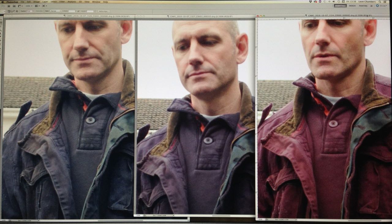
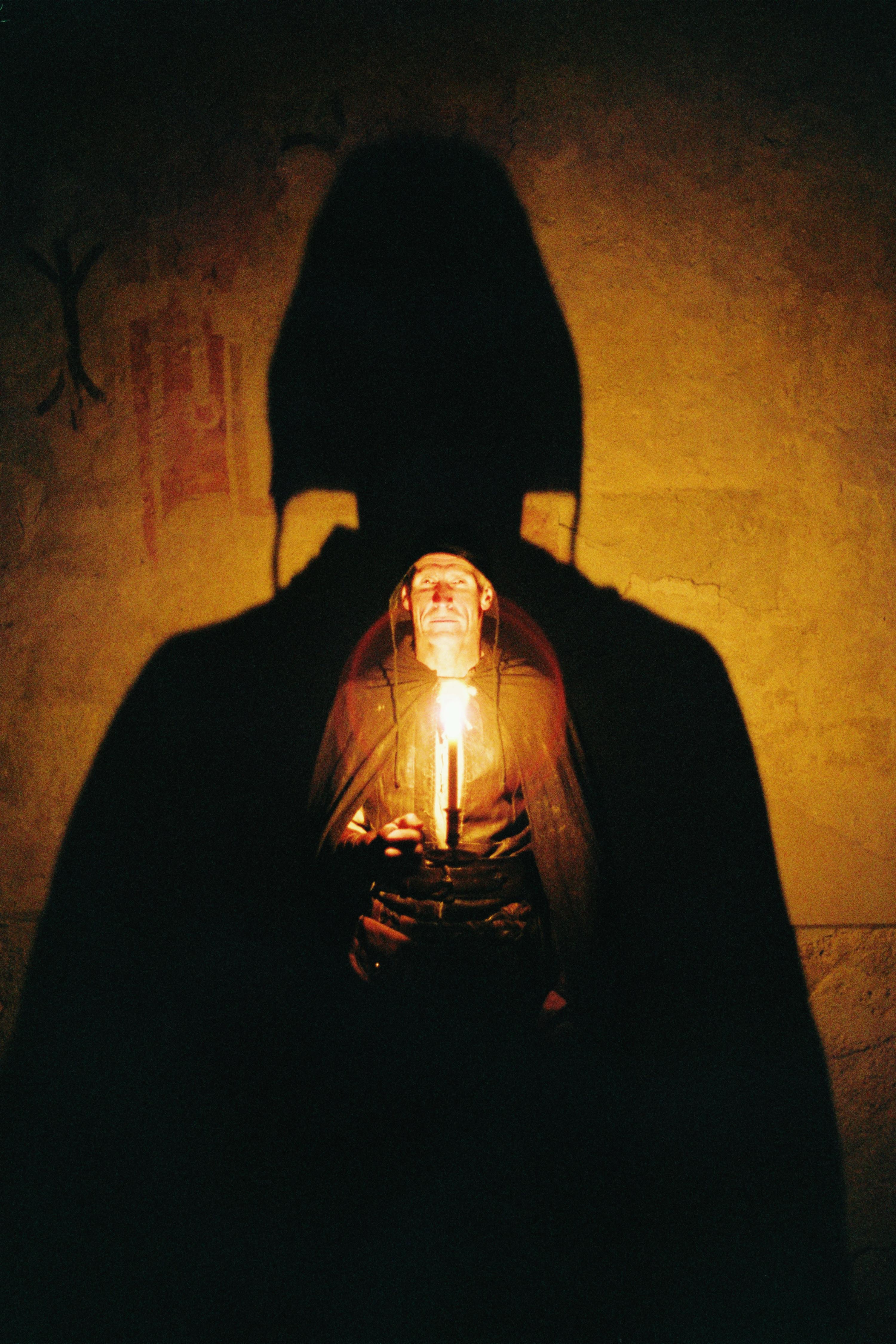
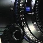
To make the whole thing a little more fun and primitive, I decided to shoot using the pinhole I made a couple of years ago. Since I plan to mount contact prints inside the zoetrope rather than enlargements, that’ll mean I’ve created and exhibited a motion picture without ever once putting the image through a lens.

I’m shooting on Ilford HP5+, a black-and-white stock with a published ISO of 400. My girlfriend bought me five roles for Christmas, which means I can potentially make ten 18-frame zoetrope inserts. I won’t be able to develop or print any of them until the lockdown ends, but that’s okay.

My first image was shot last Wednesday, a sunny day. The Sunny 16 rule tells me that at f/16 on a sunny day, my exposure should be equal to my ISO, i.e. 1/400th of a second for ISO 400. My pinhole has an aperture of f/365, which I calculated when I made it, so it’s about nine stops slower than f/16. Therefore I need to multiply that 1/400th of a second exposure time by two to the power of nine, which is 1.28 – call it one second for simplicity. ( I used my Sekonic incidence/reflectance meter to check the exposure, because it’s always wise to be sure when you haven’t got the fall-back of a digital monitor.)

One second is the longest exposure my Pentax P30t can shoot without switching to Bulb mode and timing it manually. It’s also about the longest exposure that HP5+ can do without the dreaded reciprocity failure kicking in. So all round, one second was a good exposure time to aim for.

The camera is facing roughly south, meaning that the tree is backlit and the wall of the house (which fills the background) is in shadow. This should make the tree stand out nicely. Every day may not be as sunny as today, so the light will inevitably change from frame to frame of the animation. I figured that maintaining a consistent exposure on the background wall would make the changes less jarring than trying to keep the tree’s exposure consistent.

I’ve been taking spot readings every day, and keeping the wall three-and-a-half stops under key, while the blossoms are about one stop over. I may well push the film – i.e. give it extra development time – if I end up with a lot of cloudy days where the blossoms are under key, but so far I’ve managed to catch the sun every time.

All this exposure stuff is great practice for the day when I finally get to shoot real motion picture film, should that day ever come, and it’s pretty useful for digital cinematography too.

Meanwhile, I’ve also made a rough prototype of the zoetrope itself, but more on that in a future post. Watch this space.

Shooting a Time-lapse for a Zoetrope

How Big a Light do I Need?

Experience goes a long way, but sometimes you need to be more precise about what size of lighting instruments are required for a particular scene. Night exteriors, for example; you don’t want to find out on the day that the HMI you hired as your “moon” backlight isn’t powerful enough to cover the whole of the car park you’re shooting in. How can you prep correctly so that you don’t get egg on your face?

There are two steps: 1. determine the intensity of light you require on the subject, and 2. find a combination of light fixture and fixture-to-subject distance that will provide that intensity.


The Required intensity

The goal here is to arrive at a number of foot-candles (fc). Foot-candles are a unit of light intensity, sometimes more formally called illuminance, and one foot-candle is the illuminance produced by a standard candle one foot away. (Illuminance can also be measured in the SI unit of lux, where 1 fc ≈ 10 lux, but in cinematography foot-candles are more commonly used. It’s important to remember that illuminance is a measure of the light incident to a surface, i.e. the amount of light reaching the subject. It is not to be confused with luminance, which is the amount of light reflected from a surface, or with luminous power, a.k.a. luminous flux, which is the total amount of light emitted from a source.)

Usually you start with a T-stop (or f-stop) that you want to shoot at, based on the depth of field you’d like. You also need to know the ISO and shutter interval (usually 1/48th or 1/50th of a second) you’ll be shooting at. Next you need to convert these facets of exposure into an illuminance value, and there are a few different ways of doing this.

One method is to use a light meter, if you have one, which you enter the ISO and shutter values into. Then you wave it around your office, living room or wherever, pressing the trigger until you happen upon a reading which matches your target f-stop. Then you simply switch your meter into foot-candles mode and read off the number. This method can be a bit of a pain in the neck, especially if – like mine – your meter requires fiddly flipping of dip-switches and additional calculations to get a foot-candles reading out of.

A much simpler method is to consult an exposure table, like the one below, or an exposure calculator, which I’m sure is a thing which must exist, but I’ll be damned if I could find one.

Some cinematographers memorise the fact that 100fc is f/2.8 at ISO 100, and work out other values from that. For example, ISO 400 is four times (two stops) faster than ISO 100, so a quarter of the light is required, i.e. 25fc.

Alternatively, you can use the underlying maths of the above methods. This is unlikely to be necessary in the real world, but for the purposes of this blog it’s instructive to go through the process. The equation is:

where

  • b is the illuminance in fc,
  • f is the f– or T-stop,
  • s is the shutter interval in seconds, and
  • i is the ISO.

Say I’m shooting on an Alexa with a Cooke S4 Mini lens. If I have the lens wide open at T2.8, the camera at its native ISO of 800 and the shutter interval at the UK standard of 1/50th (0.02) of a second…

… so I need about 12fc of light.


The right instrument

In the rare event that you’re actually lighting your set with candles – as covered in my Barry Lyndon and Stasis posts – then an illuminance value in fc is all you need. In every other situation, though, you need to figure out which electric light fixtures are going to give you the illuminance you need.

Manufacturers of professional lighting instruments make this quite easy for you, as they all provide data on the illuminance supplied by their products at various distances. For example, if I visit Mole Richardson’s webpage for their 1K Baby-Baby fresnel, I can click on the Performance Data table to see that this fixture will give me the 12fc (in fact slightly more, 15fc) that I required in my Alexa/Cooke example at a distance of 30ft on full flood.

Other manufacturers provide interactive calculators: on ETC’s site you can drag a virtual Source Four back and forth and watch the illuminance read-out change, while Arri offers a free iOS/Android app with similar functionality.

If you need to calculate an illuminance value for a distance not specified by the manufacturer, you can derive it from distances they do specify, by using the Inverse Square Law. However, as I found in my investigatory post about the law, that could be a whole can of worms.

If illuminance data is not available for your light source, then I’m afraid more maths is involved. For example, the room I’m currently in is lit by a bulb that came in a box marked “1,650 lumens”, which is the luminous power. One lumen is one foot-candle per square foot. To find out the illuminance, i.e. how many square feet those lumens are spread over, we imagine those square feet as the area of a sphere with the lamp at the centre, and where the radius r is the distance from the lamp to the subject. So:

where

  • is again the illuminance in fc,
  • is the luminous power of the souce in lumens, and
  • r is the lamp-to-subject distance in feet.

(I apologise for the mix of Imperial and SI units, but this is the reality in the semi-Americanised world of British film production! Also, please note that this equation is for point sources, rather than beams of light like you get from most professional fixtures. See this article on LED Watcher if you really want to get into the detail of that.)

So if I want to shoot that 12fc scene on my Alexa and Cooke S4 Mini under my 1,650 lumen domestic bulb…

… my subject needs to be 3’4″ from the lamp. I whipped out my light meter to check this, and it gave me the target T2.8 at 3’1″ – pretty close!


Do I have enough light?

If you’re on a tight budget, it may be less a case of, “What T-stop would I like to shoot at, and what fixture does that require?” and more a case of, “Is the fixture which I can afford bright enough?”

Let’s take a real example from Perplexed Music, a short film I lensed last year. We were shooting on an Alexa at ISO 1600, 1/50th sec shutter, and on Arri/Zeiss Ultra Primes, which have a maximum aperture of T1.9. The largest fixture we had was a 2.5K HMI, and I wanted to be sure that we would have enough light for a couple of night exteriors at a house location.

In reality I turned to an exposure table to find the necessary illuminance, but let’s do the maths using the first equation that we met in this post:

Loading up Arri’s photometrics app, I could see that 2.8fc wasn’t going to be a problem at all, with the 2.5K providing 5fc at the app’s maximum distance of 164ft.

That’s enough for today. All that maths may seem bewildering, but most of it is eliminated by apps and other online calculators in most scenarios, and it’s definitely worth going to the trouble of checking you have enough light before you’re on set with everyone ready to roll!

See also: 6 Ways of Judging Exposure

SaveSave

SaveSave

How Big a Light do I Need?

6 Ways to Judge Exposure

Exposing the image correctly is one of the most important parts of a cinematographer’s job. Choosing the T-stop can be a complex technical and creative decision, but fortunately there are many ways we can measure light to inform that decision.

First, let’s remind ourselves of the journey light makes: photons are emitted from a source, they strike a surface which absorbs some and reflects others – creating the impressions of colour and shade; then if the reflected light reaches an eye or camera lens it forms an image. We’ll look at the various ways of measuring light in the order the measurements occur along this light path, which is also roughly the order in which these measurements are typically used by a director of photography.


1. Photometrics data

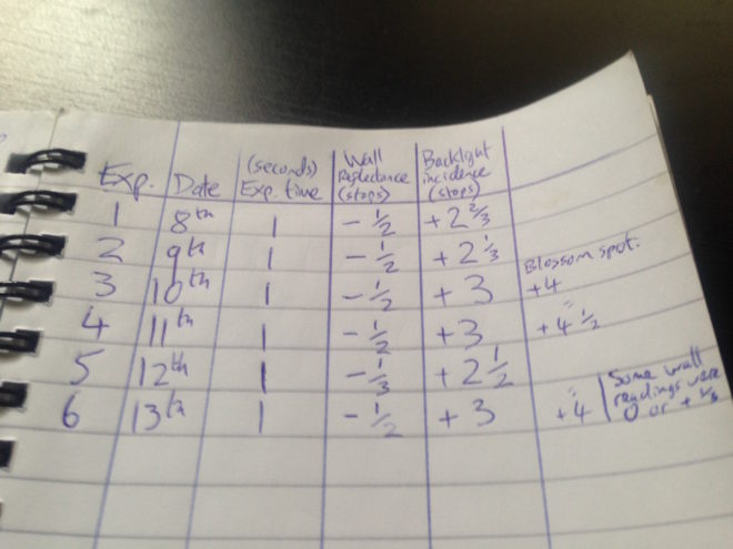
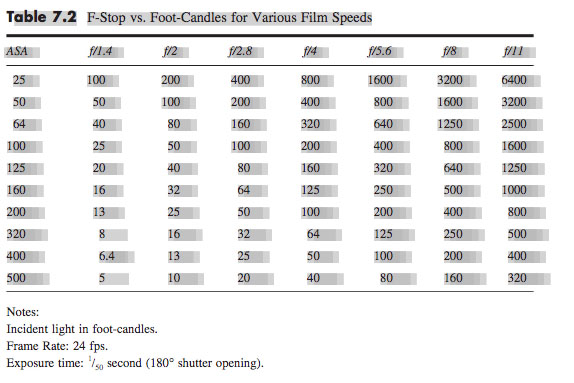
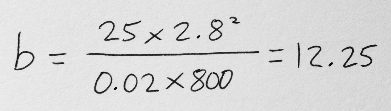
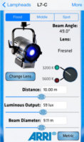
You can use data supplied by the lamp manufacturer to calculate the exposure it will provide, which is very useful in preproduction when deciding what size of lamps you need to hire. There are apps for this, such as the Arri Photometrics App, which allows you to choose one of their fixtures, specify its spot/flood setting and distance from the subject, and then tells you the resulting light level in lux or foot-candles. An exposure table or exposure calculation app will translate that number into a T-stop at any given ISO and shutter interval.


2. Incident meter

Some believe that light meters are unnecessary in today’s digital landscape, but I disagree. Most of the methods listed below require the camera, but the camera may not always be handy – on a location recce, for example. Or during production, it would be inconvenient to interrupt the ACs while they’re rigging the camera onto a crane or Steadicam. This is when having a light meter on your belt becomes very useful.

An incident meter is designed to measure the amount of light reaching the subject. It is recognisable by its white dome, which diffuses and averages the light striking its sensor. Typically it is used to measure the key, fill and backlight levels falling on the talent. Once you have input your ISO and shutter interval, you hold the incident meter next to the actor’s face (or ask them to step aside!) and point it at each source in turn, shading the dome from the other sources with your free hand. You can then decide if you’re happy with the contrast ratios between the sources, and set your lens to the T-stop indicated by the key-light reading, to ensure correct exposure of the subject’s face.


3. Spot meter (a.k.a. reflectance meter)

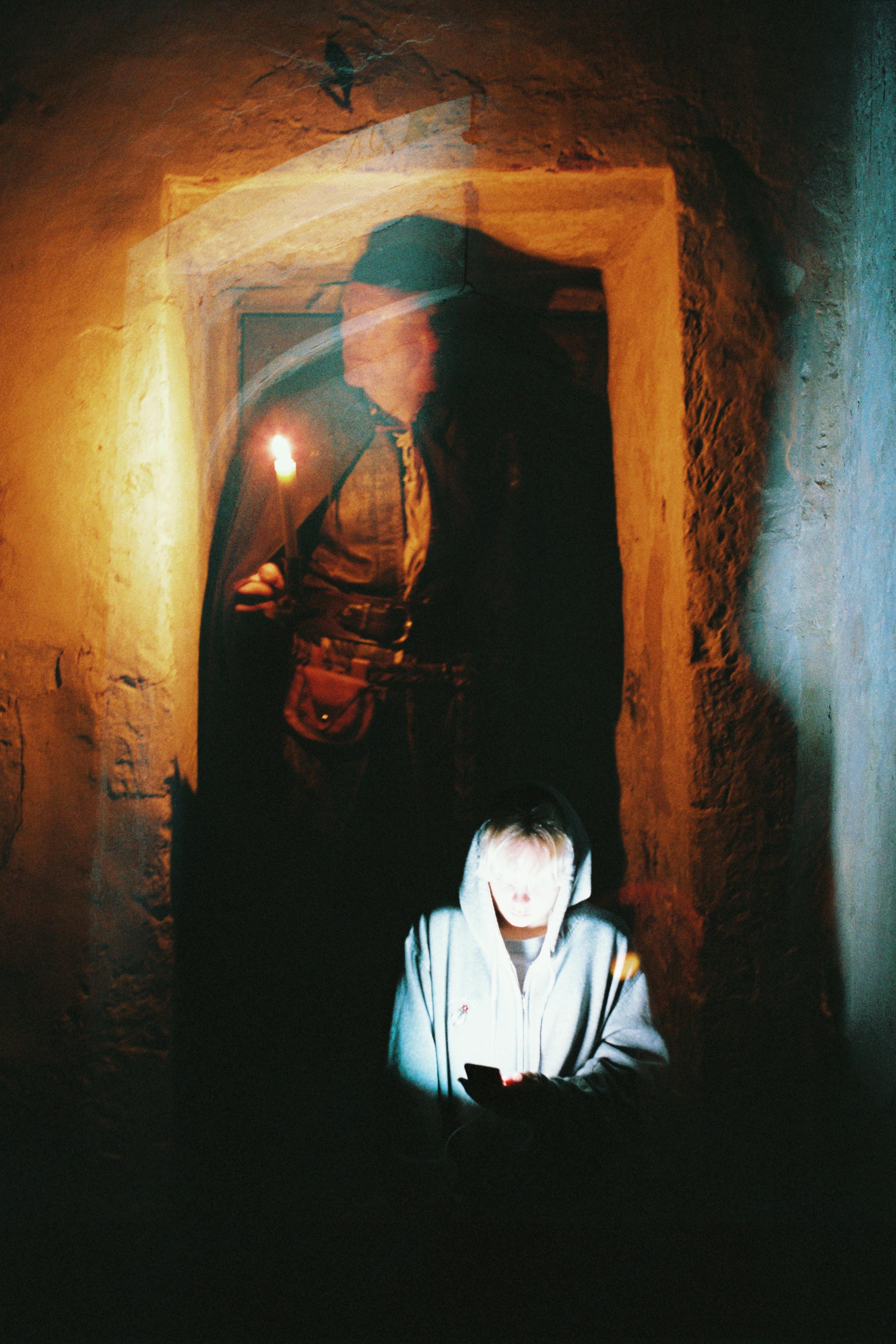
Now we move along the light path and consider light after it has been reflected off the subject. This is what a spot meter measures. It has a viewfinder with which you target the area you want to read, and it is capable of metering things that would be impractical or impossible to measure with an incident meter. If you had a bright hillside in the background of your shot, you would need to drive over to that hill and climb it to measure the incident light; with a spot meter you would simply stand at the camera position and point it in the right direction. A spot meter can also be used to measure light sources themselves: the sky, a practical lamp, a flame and so on.

But there are disadvantages too. If you spot meter a Caucasian face, you will get a stop that results in underexposure, because a Caucasian face reflects quite a lot of light. Conversely, if you spot meter an African face, you will get a stop that results in overexposure, because an African face reflects relatively little light. For this reason a spot meter is most commonly used to check whether areas of the frame other than the subject – a patch of sunlight in the background, for example – will blow out.

Your smartphone can be turned into a spot meter with a suitable app, such as Cine Meter II, though you will need to configure it using a traditional meter and a grey card. With the addition of a Luxiball attachment for your phone’s camera, it can also become an incident meter.

The remaining three methods of judging exposure which I will cover all use the camera’s sensor itself to measure the light. Therefore they take into account any filters you’re using as well transmission loss within the lens (which can be an issue when shooting on stills glass, where the marked f-stops don’t factor in transmission loss).


4. Monitors and viewfinders

The letter. Photo: Amy Nicholson

In the world of digital image capture, it can be argued that the simplest and best way to judge exposure is to just observe the picture on the monitor. The problem is, not all screens are equal. Cheap monitors can misrepresent the image in all kinds of ways, and even a high-end OLED can deceive you, displaying shadows blacker than any cinema or home entertainment system will ever match. There are only really two scenarios in which you can reliably judge exposure from the image itself: if you’ve owned a camera for a while and you’ve become very familiar with how the images in the viewfinder relate to the finished product; or if the monitor has been properly calibrated by a DIT (Digital Imaging Technician) and the screen is shielded from light.

Most cameras and monitors have built-in tools which graphically represent the luminance of the image in a much more accurate way, and we’ll look at those next. Beware that if you’re monitoring a log or RAW image in Rec.709, these tools will usually take their data from the Rec.709 image.


5. Waveforms and histograms

These are graphs which show the prevalence of different tones within the frame. Histograms are the simplest and most common. In a histogram, the horizontal axis represents luminance and the vertical axis shows the number of pixels which have that luminance. It makes it easy to see at a glance whether you’re capturing the greatest possible amount of detail, making best use of the dynamic range. A “properly” exposed image, with a full range of tones, should show an even distribution across the width of the graph, with nothing hitting the two sides, which would indicate clipped shadows and highlights. A night exterior would have a histogram crowded towards the left (darker) side, whereas a bright, low contrast scene would be crowded on the right.

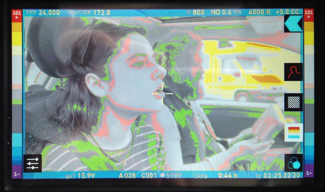
A waveform plots luminance on the vertical axis, with the horizontal axis matching the horizontal position of those luminance values within the frame. The density of the plotting reveals the prevalence of the values. A waveform that was dense in the bottom left, for example, would indicate a lot of dark tones on the lefthand side of frame. Since the vertical (luminance) axis represents IRE (Institute of Radio Engineers) values, waveforms are ideal when you need to expose to a given IRE, for example when calibrating a system by shooting a grey card. Another common example would be a visual effects supervisor requesting that a green screen be lit to 50 IRE.


6. Zebras and false colours

Almost all cameras have zebras, a setting which superimposes diagonal stripes on parts of the image which are over a certain IRE, or within a certain range of IREs. By digging into the menus you can find and adjust what those IRE levels are. Typically zebras are used to flag up highlights which are clipping (theoretically 100 IRE), or close to clipping.

Exposing an image correctly is not just about controlling highlight clipping however, it’s about balancing the whole range of tones – which brings us to false colours. A false colour overlay looks a little like a weather forecaster’s temperature map, with a code of colours assigned to various luminance values. Clipped highlights are typically red, while bright areas still retaining detail (known as the “knee” or “shoulder”) are yellow. Middle grey is often represented by green, while pink indicates the ideal level for caucasian skin tones (usually around 55 IRE). At the bottom end of the scale, blue represents the “toe” – the darkest area that still has detail – while purple is underexposed. The advantage of zebras and false colours over waveforms and histograms is that the former two show you exactly where the problem areas are in the frame.

I hope this article has given you a useful overview of the tools available for judging exposure. Some DPs have a single tool they rely on at all times, but many will use all of these methods at one time or another to produce an image that balances maximising detail with creative intent. I’ll leave you with a quote from the late, great Douglas Slocombe, BSC who ultimately used none of the above six methods!

I used to use a light meter – I used one for years. Through the years I found that, as schedules got tighter and tighter, I had less and less time to light a set. I found myself not checking the meter until I had finished the set and decided on the proper stop. It would usually say exactly what I thought it should. If it didn’t, I wouldn’t believe it, or I would hold it in such a way as to make it say my stop. After a time I decided this was ridiculous and stopped using it entirely. The “Raiders” pictures were all shot without a meter. I just got used to using my eyes.

6 Ways to Judge Exposure

Creating “Stasis”

Stasis is a personal photography project about time and light. You can view all the images here, and in this post I’ll take you through the technical and creative process of making them.

I got into cinematography directly through a love of movies and filmmaking, rather than from a fine art background. To plug this gap, over the past few of years I’ve been trying to give myself an education in art by going to galleries, and reading art and photography books. I’ve previously written about how JMW Turner’s work captured my imagination, but another artist whose work stood out to me was Gerrit (a.k.a. Gerard) Dou. Whereas most of the Dutch 17th century masters painted daylight scenes, Dou often portrayed people lit by only a single candle.

“A Girl Watering Plants” by Gerrit Dou

At around the same time as I discovered Dou, I researched and wrote a blog post about Barry Lyndon‘s groundbreaking candlelit scenes. This got me fascinated by the idea that you can correctly expose an image without once looking at a light meter or digital monitor, because tables exist giving the appropriate stop, shutter and ISO for any given light level… as measured in foot-candles. (One foot-candle is the amount of light received from a standard candle that is one foot away.)

So when I bought a 35mm SLR (a Pentax P30T) last autumn, my first thought was to recreate some of Dou’s scenes. It would be primarily an exercise in exposure discipline, training me to judge light levels and fall-off without recourse to false colours, histograms or any of the other tools available to a modern DP.

I conducted tests with Kate Madison, who had also agreed to furnish period props and costumes from the large collection which she had built up while making Born of Hope and Ren: The Girl with the Mark. Both the tests and the final images were captured on Fujifilm Superia X-tra 400. Ideally I would have tested multiple stocks, but I must confess that the costs of buying and processing several rolls were off-putting. I’d previously shot some basic latitude tests with Superia, so I had some confidence about what it could and couldn’t do. (It can be over-exposed at least five stops and still look good, but more than a stop under and it falls apart.) I therefore confined myself to experimenting with candle-to-subject distances, exposure times and filtration.

The tests showed that the concept was going to work, and also confirmed that I would need to use an 80B filter to cool the “white balance” of the film from its native daylight to tungsten (3400K). (As far as I can tell, tungsten-balanced stills film is no longer on the market.) Candlelight has a colour temperature of about 1800K, so it still reads as orange through an 80B, but without the filter it’s an ugly red.

Meanwhile, the concept had developed beyond simply recreating Gerrit Dou’s scenes. I decided to add a second character, contrasting the historical man lit only by his candle with a modern girl lit only by her phone. Flames have a hypnotic power, tapping into our ancient attraction to light, and today’s smartphones have a similarly powerful draw.

The candlelight was 1600K warmer than the filtered film, so I used an app called Colour Temp to set my iPhone to 5000K, making it 1600K cooler than the film; the phone would therefore look as blue as the candle looked orange. (Unfortunately my phone died quickly and I had trouble recharging it, so some of the last shots were done with Izzi’s non-white-balanced phone.) To match the respective colours of light, we dressed Ivan in earthy browns and Izzi in blues and greys.

Artemis recce image

We shot in St. John’s Church in Duxford, Cambridgeshire, which hasn’t been used as a place of worship since the mid-1800s. Unique markings, paintings and graffiti from the middle ages up to the present give it simultaneously a history and a timelessness, making it a perfect match to the clash of eras represented by my two characters. It resonated with the feelings I’d had when I started learning about art and realised the continuity of techniques and aims from me in my cinematography back through time via all the great artists of the past to the earliest cave paintings.

I knew from the tests that long exposures would be needed. Extrapolating from the exposure table, one foot-candle would require a 1/8th of a second shutter with my f1.4 lens wide open and the Fujifilm’s ISO of 400. The 80B has a filter factor of three, meaning you need three times more light, or, to put it another way, it cuts 1 and 2/3rds of a stop. Accounting for this, and the fact that the candle would often be more than a foot away, or that I’d want to see further into the shadows, the exposures were all at least a second long.

As time had become very much the theme of the project, I decided to make the most of these long exposures by playing with motion blur. Not only does this allow a static image – paradoxically – to show a passage of time, but it recalls 19th century photography, when faces would often blur during the long exposures required by early emulsions. Thus the history of photography itself now played a part in this time-fluid project.

I decided to shoot everything in portrait, to make it as different as possible from my cinematography work. Heavily inspired by all the classical art I’d been discovering, I used eye-level framing, often flat-on and framed architecturally with generous headroom, and a normal lens (an Asahi SMC Pentax-M 50mm/f1.4) to provide a natural field of view.

I ended up using my light meter quite a lot, though not necessarily exposing as it indicated. It was all educated guesswork, based on what the meter said and the tests I’d conducted.

I was tempted more than once to tell a definite story with the images, and had to remind myself that I was not making a movie. In the end I opted for a very vague story which can be interpreted many ways. Which of the two characters is the ghost? Or is it both of them? Are we all just ghosts, as transient as motion blur? Do we unwittingly leave an intangible imprint on the universe, like the trails of light my characters produce, or must we consciously carve our mark upon the world, as Ivan does on the wall?

Models: Izzi Godley & Ivan Moy. Stylist: Kate Madison. Assistant: Ash Maharaj. Location courtesy of the Churches Conservation Trust. Film processing and scanning by Aperture, London.

Creating “Stasis”

The Inverse Square Law

If you’ve ever read or been taught about lighting, you’ve probably heard of the Inverse Square Law. It states that light fades in proportion to the square of the distance from the source. But lately I started to wonder if this really applies in all situations. Join me as I attempt to get to the bottom of this…


Knowing the law

The seed of this post was sown almost a year ago, when I read Herbert McKay’s 1947 book The Tricks of Light and Colour, which described the Inverse Square Law in terms of light spreading out. (Check out my post about The Tricks of Light and Colour here.)

But before we go into that, let’s get the Law straight in our minds. What, precisely, does it say? Another excellent book, Gerald Millerson’s Lighting for Television and Film, defines it thusly:

With increased distance, the light emitted from a given point source will fall rapidly, as it spreads over a progressively larger area. This fall-off in light level is inversely proportional to the distance square, i.e. 1/d². Thus, doubling the lamp distance would reduce the light to ¼.

The operative word, for our purposes, is “spreads”.

If you’d asked me a couple of years ago what causes the Inverse Square Law, I probably would have mumbled something about light naturally losing energy as it travels. But that is hogwash of the highest order. Assuming the light doesn’t strike any objects to absorb it, there is nothing to reduce its energy. (Air does scatter – and presumably absorb – a very small amount of light, hence atmospheric haze, but this amount will never be significant on the scale a cinematographer deals with.)

In fact, as the Millerson quote above makes clear, the Inverse Square Law is a result of how light spreads out from its source. It’s purely geometry. In this diagram you can see how fewer and fewer rays strike the ‘A’ square as it gets further and further away from the source ‘S’:

Illustration by Borb, CC BY-SA 3.0

Each light ray (dodgy term, I know, but sufficient for our purposes) retains the same level of energy, and there are the same number of them overall, it’s just that there are fewer of them passing through any given area.

So far, so good.


Taking the Law into my own hands

During season two of my YouTube series Lighting I Like, I discussed Dedo’s Panibeam 70 HMI. This fixture produces collimated light, light of which all the waves are travelling in parallel. It occurred to me that this must prevent them spreading out, and therefore render the Inverse Square Law void.

This in turn got me thinking about more common fixtures – par cans, for example.


Par lamps are so named for the Parabolic Aluminised Reflectors they contain. These collect the light radiated from the rear and sides of the filament and reflect it as parallel rays. So to my mind, although light radiated from the very front of the filament must still spread and obey the Inverse Square Law, that which bounces off the reflector should theoretically never diminish. You can imagine that the ‘A’ square in our first diagram would have the same number of light rays passing through it every time if they are travelling in parallel.

Similarly, fresnel lenses are designed to divert the spreading light waves into a parallel pattern:

Even simple open-face fixtures have a reflector which can be moved back and forth using the flood/spot control, affecting both the spread and the intensity of the light. Hopefully by now you can see why these two things are related. More spread = more divergence of light rays = more fall-off. Less spread = less divergence of light rays = more throw.

So, I wondered, am I right? Do these focused sources disobey the Inverse Square Law?


Breaking the law

To find the answer, I waded through a number of fora.

Firstly, and crucially, everyone agrees that the Law describes light radiated from a point source, so any source which isn’t infinitely small will technically not be governed by the Law. In practice, says the general consensus, the results predicted by the Law hold true for most sources, unless they are quite large or very close to the subject.

If you are using a softbox, a Kinoflo or a trace frame at short range though, the Inverse Square Law will not apply.

The above photometric data for a Filmgear LED Flo-box indeed shows a slower fall-off than the Law predicts. (Based on the 1m intensity, the Law predicts the 2m and 3m intensities as 970÷2²=243 lux and 970÷3²=108 lux respectively.)

A Flickr forum contributor called Severin Sadjina puts it like this:

In general, the light will fall off as 1/d² if the size of the light source is negligible compared to the distance d to the light source. If, on the other hand, the light source is significantly larger than the distance d to the light source, the light will fall off as 1/d – in other words: slower than the Inverse Square Law predicts.

Another contributor, Ftir, claims that a large source will start to follow the Law above distances equal to about five times the largest side of the source, so a 4ft Kinoflo would obey the Law very closely after about 20ft. This claim is confirmed by Wikipedia, citing A. Ryer’s The Light Measurement Handbook.

But what about those pesky parallel light beams from the pars and fresnels?

Every forum had a lot of disagreement on this. Most people agree that parallel light rays don’t really exist in real life. They will always diverge or converge, slightly, and therefore the Law applies. However, many claim that it doesn’t apply in quite the same way.

Diagram from a tutorial PDF on light-measurement.com showing a virtual point source behind the bulb of a torch.

A fresnel, according to John E. Clark on Cinematography.com, can still be treated as a point source, but that point source is actually located somewhere behind the lamp-head! It’s a virtual point source. (Light radiating from a distant point source has approximately parallel rays with consequently negligible fall-off, e.g. sunlight.) So if this virtual source is 10m behind the fixture, then moving the lamp from 1m from the subject to 2m is not doubling the distance (and therefore not quartering the intensity). In fact it is multiplying the distance by 1.09 (12÷11=1.09), so the light would only drop to 84% of its former intensity (1÷1.09²=0.84).

I tried to confirm this using the Arri Photometrics App, but the data it gives for Arri’s fresnel fixtures conforms perfectly with an ordinary point source under the Law, leaving me somewhat confused. However, I did find some data for LED fresnels that broke the Law, for example the Lumi Studio 300:

As you can see, at full flood (bottom graphic) the Law is obeyed as expected; the 8m intensity of 2,500 lux is a quarter of the 4m intensity of 10,000 lux. But when spotted (top graphic) it falls off more rapidly. Again, very confusing, as I was expecting it to fall off less rapidly if the rays are diverging but close to parallel.

A more rapid fall-off suggests a virtual point source somewhere in front of the lamp-head. This was mentioned in several places on the fora as well. The light is converging, so the intensity increases as you move further from the fixture, reaching a maximum at the focal point, then diverging again from that point as per the Inverse Square Law. In fact, reverse-engineering the above data using the Law tells me – if my maths is correct – that the focal point is 1.93m in front of the fixture. Or, to put it another way, spotting this fixture is equivalent to moving it almost 2m closer to the subject. However, this doesn’t seem to tally with the beam spread data in the above graphics. More confusion!

I decided to look up ETC’s Source Four photometrics, since these units contain an ellipsoidal reflector which should focus the light (and therefore create a virtual point source) in front of themselves. However, the data shows no deviation from the Law and no evidence of a virtual point source displaced from the actual source.


I fought the law and the law won

I fear this investigation has left me more confused than when I started! Clearly there are factors at work here beyond what I’ve considered.

However, I’ve learnt that the Inverse Square Law is a useful means of estimating light fall-off for most lighting fixtures – even those that really seem like they should act differently! If you double the distance from lamp to subject, you’re usually going to quarter the intensity, or near as damn it. And that rule of thumb is all we cinematographers need 99% of the time. If in doubt, refer to photometrics data like that linked above.

And if anyone out there can shed any light (haha) on the confusion, I’d be very happy to hear from you!

The Inverse Square Law

Choosing an ND Filter: f-stops, T-stops and Optical Density

A revised and updated version of this article can be found here (aperture) and here (ND filters).

Imagine this scenario. I’m lensing a daylight exterior and my light meter gives me a reading of f/11, but I want to shoot with an aperture of T4, because that’s the depth of field I like. I know that I need to use a .9 ND (neutral density) filter. But how did I work that out? How on earth does anyone arrive at the number 0.9 from the numbers 11 and 4?

Let me explain from the beginning. First of all, let’s remind ourselves what f-stops are. You have probably seen those familiar numbers printed on the sides of lenses many times…

1      1.4      2      2.8      4      5.6      8      11      16      22

They are ratios: ratios of the lens’ focal length to its iris diameter. So a 50mm lens with a 25mm diameter iris is at f/2. If you close up the iris to just under 9mm in diameter, you’ll be at f/5.6 (50 divided by 5.6 is 8.93).

A stills lens with its aperture ring marked in f-stops
A stills lens with its aperture ring (top) marked in f-stops

But why not label a lens 1, 2, 3, 4? Why 1, 1.2, 2, 2.8…? These magic numbers are f-stops. A lens set to f/1 will let in twice as much light as (or ‘one stop more than’) one set to f/1.4, which in turn will let in twice as much as one set to f/2, and so on. Conversely, a lens set to f/2 will let in half as much light as (or ‘one stop less than’) one set to f/1.4, and so on.


If you think back to high school maths and the Pi r squared formula for calculating the area of a circle from its radius, the reason for the seemingly random series of numbers will start to become clear. Letting in twice as much light requires twice as much area for those light rays to fall on, and remember that the f-number is the ratio of the focal length to the iris diameter, so you can see how square roots are going to get involved and why f-stops aren’t just plain old round numbers.

A Zeiss Compact Prime lens with its aperture ring marked in T-stops

Now, earlier I mentioned T4. How did I get from f-stops to T-stops? Well, T-stops are f-stops adjusted to compensate for the light transmission efficiency. Two different f/2 lenses will not necessarily produce equally bright images, because some percentage of light travelling through the elements will always be lost, and that percentage will vary depending on the quality of the glass and the number of elements. A lens with 100% light transmission would have the same f-number and T-number, but in practice the T-number will always be a little higher than the f-number. For example, Cooke’s 15-40mm zoom is rated at a maximum aperture of T2 or f/1.84.

So, let’s go back to my original scenario and see where we are. My light meter reads f/11. However,  I expressed my target stop as a T-number though, T4, because I’m using cinema lenses and they’re marked up in T-stops rather than f-stops. (I can still use the f-number my meter gives me though; in fact if my lens were marked in f-stops then my exposure would be slightly off because the meter does not know the transmission efficiency of my lens.)

By looking at the series of f-numbers permanently displayed on my light meter (the same series listed near the top of this post, or on any lens barrel) I can see that f/11 (or T11) is 3 stops above f/4 (or T4) – because 11 is three numbers to the right of 4 in the series. I can often be seen on set counting the stops like this on my light meter or on my fingers. It is of course possible to work it out mathematically, but screw that!

CameraZOOM-20140309092150072_zps94e90ea4
A set of Tiffen 4×4″ ND filters

So I need an ND filter that cuts 3 stops of light. But we’re not out of the mathematical woods yet.

The most popular ND filters amongst professional cinematographers are those made by Tiffen, and a typical set might be labelled as follows:

.3      .6      .9      1.2

Argh! What do those numbers mean? That’s the optical density, a property defined as the natural logarithm of the ratio of the quantity of light entering the filter to the quantity of light exiting it on the other side. A .3 ND reduces the light by half because 10 raised to the power of -0.3 is 0.5, or near as damn it. And reducing light by half, as we established earlier, means dropping one stop.

If that fries your brain, don’t worry; it does mine too. All you really need to do is multiply the number of stops you want to drop by 0.3 to find the filter you need. So to drop three stops you pick the .9 ND.

And that’s why you need a .9 ND to shoot at T4 when your light meter says f/11. Clear as mud, right? Once you get your head around it, and memorise the f-stops, this all becomes a lot easier than it seems at first glance.

Here are a couple more examples:

  • Light meter reads f/8 and you want to shoot at T5.6. That’s a one stop difference. (5.6 and 8 are right next to each other in the stop series, as you’ll see if you scroll back to the top.) 1 x 0.3 = 0.3 so you should use the .3 ND.
  • Light meter reads f/22 and you want to shoot at T2.8. That’s a six stop difference (scroll back up and count them), and 6 x 0.3 = 1.8, so you need a 1.8 ND filter. If you don’t have one, you need to stack two NDs in your matte box that add up to 1.8, e.g. a 1.2 and a .6.


Choosing an ND Filter: f-stops, T-stops and Optical Density