Making a Pinhole Attachment for an SLR

Last autumn, after a few years away from it, I got back into 35mm stills photography. I’ve been reading a lot of books about photography: the art of it, the science and the history too. I’ve even taken a darkroom course to learn how to process and print my own black and white photos.

Shooting stills in my spare time gives me more opportunities to develop my eye for composition, my exposure-judging skills and my appreciation of natural light. Beyond that, I’ve discovered interesting parallels between electronic and photochemical imaging which enhance my understanding of both.

For example, I used to think of changing the ISO on a digital camera as analogous to loading a different film stock into a traditional camera. However, I’ve come to realise it’s more like changing the development time – it’s an after-the-fact adjustment to an already-captured (latent) image. There’s more detail on this analogy in my ISO article at Red Shark News.

The importance of rating an entire roll of film at the same exposure index, as it must all be developed for the same length of time, also has resonance in the digital world. Maintaining a consistency of exposure (or the same LUT) throughout a scene or sequence is important in digital filmmaking because it makes the dailies more watchable and reduces the amount of micro-correction which the colourist has to do down the line.

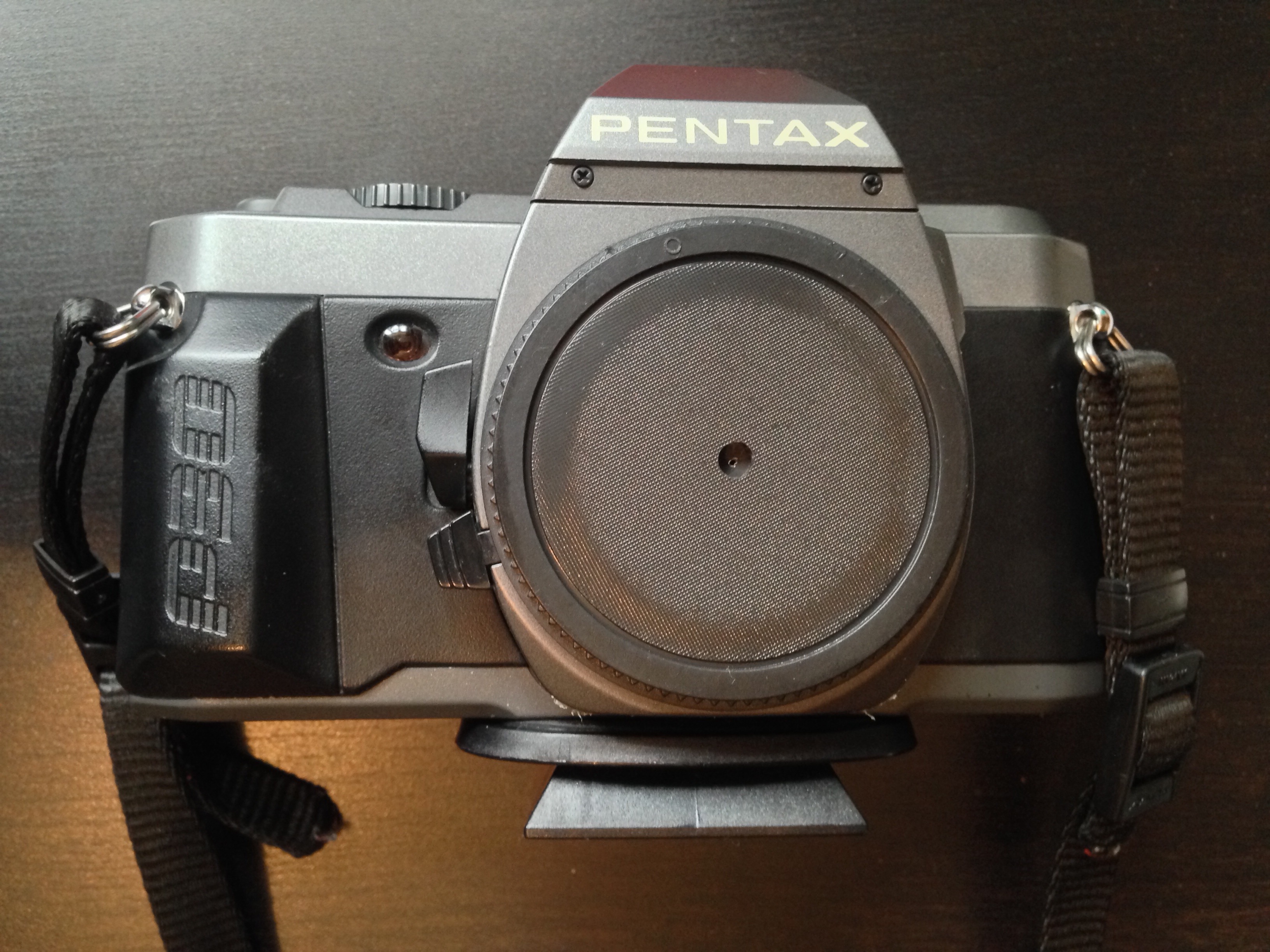
Anyway, this is all a roundabout way of explaining why I decided to make a pinhole attachment for my SLR this week. It’s partly curiosity, partly to increase my understanding of image-making from first principles.

The pinhole camera is the simplest image-making device possible. Because light rays travel in straight lines, when they pass through a very small hole they emerge from the opposite side in exactly the same arrangement, only upside-down, and thus form an image on a flat surface on the other side. Make that flat surface a sheet of film or a digital sensor and you can capture this image.


How to make a pinhole attachment

I used Experimental Filmmaking: Break the Machine by Kathryn Ramey as my guide, but it’s really pretty straightforward.

You will need:

  • an extra body cap for your camera,
  • a drill,
  • a small piece of smooth, non-crumpled black wrap, or kitchen foil painted black,
  • scissors,
  • gaffer tape (of course), and
  • a needle or pin.

Instructions:

  1. Drill a hole in the centre of the body cap. The size of the hole is unimportant.
  2. Use the pin or needle to pierce a hole in the black wrap, at least a couple of centimetres from the edge.
  3. Cut out a rough circle of the black wrap, with the pinhole in the middle. This circle needs to fit on the inside of the body cap, with the pinhole in the centre of the drilled hole.
  4. Use the gaffer tape to fix the black wrap tightly to the inside of the body cap.
  5. Fit the body cap to your camera.

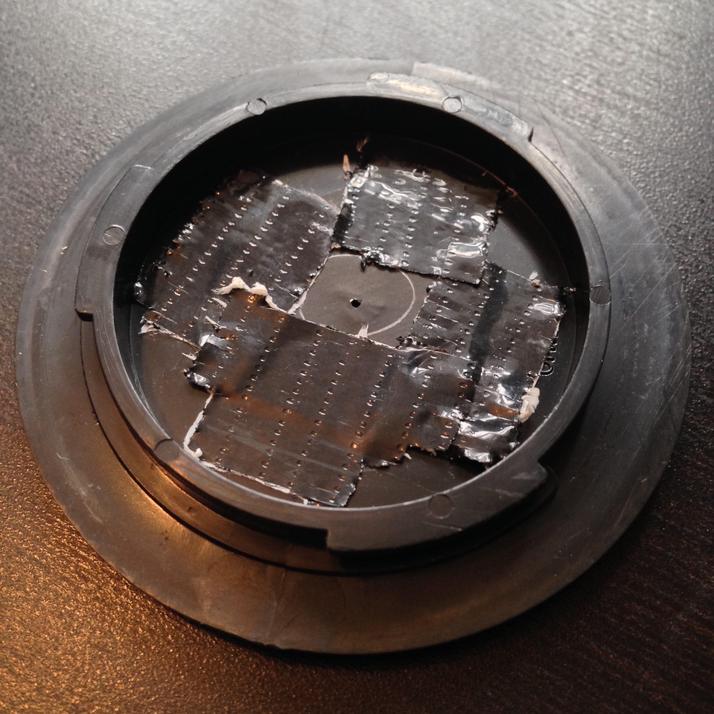
The smaller the pinhole is, the sharper the image will be, but the darker too. The first pinhole I made was about 0.1-0.2mm in diameter, but when I fitted it to my camera and looked through the viewfinder I could hardly make anything out at all. So I made a second one, this time pushing the pin properly through the black wrap, rather than just pricking it with the tip. (Minds out of the gutter, please.) The new hole was about 0.7mm but still produced an incredibly dark image in the viewfinder.


Exposing a pinhole image

If you’re using a digital camera, you can of course judge your exposure off the live-view screen. Things are a little more complicated if, like me, you’re shooting on film.

In theory the TTL (through the lens) light meter should give me just as reliable a reading as it would with a lens. The problem is that, even with the shutter set to 1 second, and ISO 400 Fujifilm Super X-tra loaded, the meter tells me I’m underexposed. Admittedly the weather has been overcast since I made the pinhole yesterday, so I may get a useful reading when the sun decides to come out again.

Failing that, I can use my handheld incident-light meter to determine the exposure…. once I’ve worked out what the f-stop of my pinhole is.

As I described in my article on aperture settings, the definition of an f-stop is: the ratio of the focal length to the aperture diameter. We’re all used to using lenses that have a clearly defined and marked focal length, but what is the focal length in a pinhole system?

The definition of focal length is the distance between the point where the light rays focus (i.e. converge to a point) and the image plane. So the focal length of a pinhole camera is very simply the distance from the pinhole itself to the film or digital sensor. Since my pinhole is more or less level with the top of the lens mount, the focal length is going to be approximately equal to the camera’s flange focal distance (defined as the distance between the lens mount and the image plane). According to Wikipedia, the flange focal distance for a Pentax K-mount camera is 45.46mm.

So the f-stop of my 0.7mm pinhole is f/64, because 45.64 ÷ 0.7 ≈ 64. Conveniently, f/64 is the highest stop my light meter will handle.

The website Mr Pinhole has a calculator to help you figure this sort of stuff out, and it even tells you the optimal pinhole diameter for your focal length. Apparently this is 0.284mm in my case, so my images are likely to be quite soft.

Anyway, when the sun comes out I’ll take some pictures and let you know how I get on!

Making a Pinhole Attachment for an SLR

The Normal Lens

Today I’m investigating the so-called normal (a.k.a. standard) lens, finding out exactly what it is, the history behind it, and how it’s relevant to contemporary cinematographers.


The Normal lens in still photography

A normal lens is one whose focal length is equal to the measurement across the diagonal of the recorded image. This gives an angle of view of about 53°, which is roughly equivalent to that of the human eye, at least the angle within which the eye can see detail. If a photo taken with a normal lens is printed and held up in front of the real scene, with the distance from the observer to the print being equal to the diagonal of the print, then objects in the photo will look exactly the same size as the real objects.

Asahi Pentax-M 50mm/f1.4 – a normal lens for 35mm stills

Lenses with a shorter focal length than the normal are known as wide-angle. Lenses with a greater focal length than the normal are considered to be long lenses. (Sometimes you will hear the term telephoto used interchangeably with long lens, but a telephoto lens is technically one which has a focal length greater than its physical length.)

A still 35mm negative is 43.3mm across the diagonal, but this got rounded up quite a bit — by Leica inventor Oskar Barnack — so that 50mm is widely considered to be the normal lens in the photography world. Indeed, some photographers rarely stray from the 50mm. For some this is simply because of its convenience; it is the easiest length of lens to manufacture, and therefore the cheapest and lightest. Because it’s neither too short nor too long, all types of compositions can be achieved with it. Other photographers are more dogmatic, considering a normal lens the only authentic way to capture an image, believing that any other length falsifies or distorts perspective.


The normal lens in cinematography

SMPTE (the Society of Motion Picture and Television Engineers), or indeed SMPE as it was back then, decided almost a century ago that a normal lens for motion pictures should be one with a focal length equal to twice the image diagonal. They reasoned that this would give a natural field of view to a cinema-goer sitting in the middle of the auditorium, halfway between screen and projector (the latter conventionally fitted with a lens twice the length of the camera’s normal lens).

A Super-35 digital cinema sensor – in common with 35mm motion picture film – has a diagonal of about 28mm. According to SMPE, this gives us a normal focal length of 56mm. Acclaimed twentieth century directors like Hitchcock, Robert Bresson and Yasujiro Ozu were proponents of roughly this focal length, 50mm to be more precise, believing it to have the most natural field of view.

Of course, the 1920s SMPE committee, living in a world where films were only screened in cinemas, could never have predicted the myriad devices on which movies are watched today. Right now I’m viewing my computer monitor from a distance about equal to the diagonal of the screen, but to hold my phone at the distance of its diagonal would make it uncomfortably close to my face. Large movie screens are still closer to most of the audience than their diagonal measurement, just as they were in the twenties, but smaller multiplex screens may be further away than their diagonals, and TV screens vary wildly in size and viewing distance.


The new normal

To land in the middle of the various viewing distances common today, I would argue that filmmakers should revert to the photography standard of a normal focal length equal to the diagonal, so 28mm for a Super-35 sensor.

Deleted scene from “Ren: The Girl with the Mark” shot on a vintage 28mm Pentax-M

According to Noam Kroll, “Spielberg, Scorsese, Orson Wells, Malick, and many other A-list directors have cited the 28mm lens as one of their most frequently used and in some cases a favorite [sic]”.

I have certainly found lenses around that length to be the most useful on set.  A 32mm is often my first choice for handheld, Steadicam, or anything approaching a POV. It’s great for wides because it compresses things a little and crops out unnecessary information while still taking plenty of the scene in. It’s also good for mids and medium close-ups, making the viewer feel involved in the conversation.

When I had to commit to a single prime lens to seal up in a splash housing for a critical ocean scene in The Little Mermaid, I quickly chose a 32mm, knowing that I could get wides and tights just by repositioning myself.

A scene from “The Little Mermaid” which I shot on a 32mm Cooke S4

I’ve found a 32mm useful in situations where coverage was limited. Many scenes in Above the Clouds were captured as a simple shot-reverse: both mids, both on the 32mm. This was done partly to save time, partly because most of the sets were cramped, and partly because it was a very effective way to get close to the characters without losing the body language, which was essential for the comedy. We basically combined the virtues of wides and close-ups into a single shot size!

In addition to the normal lens’ own virtues, I believe that it serves as a useful marker post between wide lenses and long lenses. In the same way that an editor should have a reason to cut, in a perfect world a cinematographer should have a reason to deviate from the normal lens. Choose a lens shorter than the normal and you are deliberately choosing to expand the space, to make things grander, to enhance perspective and push planes apart. Select a lens longer than the normal and you’re opting for portraiture, compression, stylisation, maybe even claustrophobia. Thinking about all this consciously and consistently throughout a production can add immeasurably to the impact of the story.

The Normal Lens

How Big a Light do I Need?

Experience goes a long way, but sometimes you need to be more precise about what size of lighting instruments are required for a particular scene. Night exteriors, for example; you don’t want to find out on the day that the HMI you hired as your “moon” backlight isn’t powerful enough to cover the whole of the car park you’re shooting in. How can you prep correctly so that you don’t get egg on your face?

There are two steps: 1. determine the intensity of light you require on the subject, and 2. find a combination of light fixture and fixture-to-subject distance that will provide that intensity.


The Required intensity

The goal here is to arrive at a number of foot-candles (fc). Foot-candles are a unit of light intensity, sometimes more formally called illuminance, and one foot-candle is the illuminance produced by a standard candle one foot away. (Illuminance can also be measured in the SI unit of lux, where 1 fc ≈ 10 lux, but in cinematography foot-candles are more commonly used. It’s important to remember that illuminance is a measure of the light incident to a surface, i.e. the amount of light reaching the subject. It is not to be confused with luminance, which is the amount of light reflected from a surface, or with luminous power, a.k.a. luminous flux, which is the total amount of light emitted from a source.)

Usually you start with a T-stop (or f-stop) that you want to shoot at, based on the depth of field you’d like. You also need to know the ISO and shutter interval (usually 1/48th or 1/50th of a second) you’ll be shooting at. Next you need to convert these facets of exposure into an illuminance value, and there are a few different ways of doing this.

One method is to use a light meter, if you have one, which you enter the ISO and shutter values into. Then you wave it around your office, living room or wherever, pressing the trigger until you happen upon a reading which matches your target f-stop. Then you simply switch your meter into foot-candles mode and read off the number. This method can be a bit of a pain in the neck, especially if – like mine – your meter requires fiddly flipping of dip-switches and additional calculations to get a foot-candles reading out of.

A much simpler method is to consult an exposure table, like the one below, or an exposure calculator, which I’m sure is a thing which must exist, but I’ll be damned if I could find one.

Some cinematographers memorise the fact that 100fc is f/2.8 at ISO 100, and work out other values from that. For example, ISO 400 is four times (two stops) faster than ISO 100, so a quarter of the light is required, i.e. 25fc.

Alternatively, you can use the underlying maths of the above methods. This is unlikely to be necessary in the real world, but for the purposes of this blog it’s instructive to go through the process. The equation is:

where

  • b is the illuminance in fc,
  • f is the f– or T-stop,
  • s is the shutter interval in seconds, and
  • i is the ISO.

Say I’m shooting on an Alexa with a Cooke S4 Mini lens. If I have the lens wide open at T2.8, the camera at its native ISO of 800 and the shutter interval at the UK standard of 1/50th (0.02) of a second…

… so I need about 12fc of light.


The right instrument

In the rare event that you’re actually lighting your set with candles – as covered in my Barry Lyndon and Stasis posts – then an illuminance value in fc is all you need. In every other situation, though, you need to figure out which electric light fixtures are going to give you the illuminance you need.

Manufacturers of professional lighting instruments make this quite easy for you, as they all provide data on the illuminance supplied by their products at various distances. For example, if I visit Mole Richardson’s webpage for their 1K Baby-Baby fresnel, I can click on the Performance Data table to see that this fixture will give me the 12fc (in fact slightly more, 15fc) that I required in my Alexa/Cooke example at a distance of 30ft on full flood.

Other manufacturers provide interactive calculators: on ETC’s site you can drag a virtual Source Four back and forth and watch the illuminance read-out change, while Arri offers a free iOS/Android app with similar functionality.

If you need to calculate an illuminance value for a distance not specified by the manufacturer, you can derive it from distances they do specify, by using the Inverse Square Law. However, as I found in my investigatory post about the law, that could be a whole can of worms.

If illuminance data is not available for your light source, then I’m afraid more maths is involved. For example, the room I’m currently in is lit by a bulb that came in a box marked “1,650 lumens”, which is the luminous power. One lumen is one foot-candle per square foot. To find out the illuminance, i.e. how many square feet those lumens are spread over, we imagine those square feet as the area of a sphere with the lamp at the centre, and where the radius r is the distance from the lamp to the subject. So:

where

  • is again the illuminance in fc,
  • is the luminous power of the souce in lumens, and
  • r is the lamp-to-subject distance in feet.

(I apologise for the mix of Imperial and SI units, but this is the reality in the semi-Americanised world of British film production! Also, please note that this equation is for point sources, rather than beams of light like you get from most professional fixtures. See this article on LED Watcher if you really want to get into the detail of that.)

So if I want to shoot that 12fc scene on my Alexa and Cooke S4 Mini under my 1,650 lumen domestic bulb…

… my subject needs to be 3’4″ from the lamp. I whipped out my light meter to check this, and it gave me the target T2.8 at 3’1″ – pretty close!


Do I have enough light?

If you’re on a tight budget, it may be less a case of, “What T-stop would I like to shoot at, and what fixture does that require?” and more a case of, “Is the fixture which I can afford bright enough?”

Let’s take a real example from Perplexed Music, a short film I lensed last year. We were shooting on an Alexa at ISO 1600, 1/50th sec shutter, and on Arri/Zeiss Ultra Primes, which have a maximum aperture of T1.9. The largest fixture we had was a 2.5K HMI, and I wanted to be sure that we would have enough light for a couple of night exteriors at a house location.

In reality I turned to an exposure table to find the necessary illuminance, but let’s do the maths using the first equation that we met in this post:

Loading up Arri’s photometrics app, I could see that 2.8fc wasn’t going to be a problem at all, with the 2.5K providing 5fc at the app’s maximum distance of 164ft.

That’s enough for today. All that maths may seem bewildering, but most of it is eliminated by apps and other online calculators in most scenarios, and it’s definitely worth going to the trouble of checking you have enough light before you’re on set with everyone ready to roll!

See also: 6 Ways of Judging Exposure

SaveSave

SaveSave

How Big a Light do I Need?

Colour Rendering Index

Many light sources we come across today have a CRI rating. Most of us realise that the higher the number, the better the quality of light, but is it really that simple? What exactly is Colour Rendering Index, how is it measured and can we trust it as cinematographers? Let’s find out.


What is C.R.I.?

CRI was created in 1965 by the CIE – Commission Internationale de l’Eclairage – the same body responsible for the colour-space diagram we met in my post about How Colour Works. The CIE wanted to define a standard method of measuring and rating the colour-rendering properties of light sources, particularly those which don’t emit a full spectrum of light, like fluorescent tubes which were becoming popular in the sixties. The aim was to meet the needs of architects deciding what kind of lighting to install in factories, supermarkets and the like, with little or no thought given to cinematography.

As we saw in How Colour Works, colour is caused by the absorption of certain wavelengths of light by a surface, and the reflection of others. For this to work properly, the light shining on the surface in the first place needs to consist of all the visible wavelengths. The graphs below show that daylight indeed consists of a full spectrum, as does incandescent lighting (e.g. tungsten), although its skew to the red end means that white-balancing is necessary to restore the correct proportions of colours to a photographed image. (See my article on Understanding Colour Temperature.)

Fluorescent and LED sources, however, have huge peaks and troughs in their spectral output, with some wavelengths missing completely. If the wavelengths aren’t there to begin with, they can’t reflect off the subject, so the colour of the subject will look wrong.

Analysing the spectrum of a light source to produce graphs like this required expensive equipment, so the CIE devised a simpler method of determining CRI, based on how the source reflected off a set of eight colour patches. These patches were murky pastel shades taken from the Munsell colour wheel (see my Colour Schemes post for more on colour wheels). In 2004, six more-saturated patches were added.

The maths which is used to arrive at a CRI value goes right over my head, but the testing process boils down to this:

  1. Illuminate a patch with daylight (if the source being tested has a correlated colour temperature of 5,000K or above) or incandescent light (if below 5,000K).
  2. Compare the colour of the patch to a colour-space CIE diagram and note the coordinates of the corresponding colour on the diagram.
  3. Now illuminate the patch with the source being tested.
  4. Compare the new colour of the patch to the CIE diagram and note the coordinates of the corresponding colour.
  5. Calculate the distance between the two sets of coordinates, i.e. the difference in colour under the two light sources.
  6. Repeat with the remaining patches and calculate the average difference.

Here are a few CRI ratings gleaned from around the web:

Source CRI
Sodium streetlight -44
Standard fluorescent 50-75
Standard LED 83
LitePanels 1×1 LED 90
Arri HMI 90+
Kino Flo 95
Tungsten 100 (maximum)


Problems with C.R.I.

There have been many criticisms of the CRI system. One is that the use of mean averaging results in a lamp with mediocre performance across all the patches scoring the same CRI as a lamp that does terrible rendering of one colour but good rendering of all the others.

Demonstrating the non-continuous spectrum of a fluorescent lamp, versus the continuous spectrum of incandescent, using a prism.

Further criticisms relate to the colour patches themselves. The eight standard patches are low in saturation, making them easier to render accurately than bright colours. An unscrupulous manufacturer could design their lamp to render the test colours well without worrying about the rest of the spectrum.

In practice this all means that CRI ratings sometimes don’t correspond to the evidence of your own eyes. For example, I’d wager that an HMI with a quoted CRI in the low nineties is going to render more natural skin-tones than an LED panel with the same rating.

I prefer to assess the quality of a light source by eye rather than relying on any quoted CRI value. Holding my hand up in front of an LED fixture, I can quickly tell whether the skin tones looks right or not. Unfortunately even this system is flawed.

The fundamental issue is the trichromatic nature of our eyes and of cameras: both work out what colour things are based on sensory input of only red, green and blue. As an analogy, imagine a wall with a number of cracks in it. Imagine that you can only inspect it through an opaque barrier with three slits in it. Through those three slits, the wall may look completely unblemished. The cracks are there, but since they’re not aligned with the slits, you’re not aware of them. And the “slits” of the human eye are not in the same place as the slits of a camera’s sensor, i.e. the respective sensitivities of our long, medium and short cones do not quite match the red, green and blue dyes in the Bayer filters of cameras. Under continuous-spectrum lighting (“smooth wall”) this doesn’t matter, but with non-continuous-spectrum sources (“cracked wall”) it can lead to something looking right to the eye but not on camera, or vice-versa.


Conclusion

Given its age and its intended use, it’s not surprising that CRI is a pretty poor indicator of light quality for a modern DP or gaffer. Various alternative systems exist, including GAI (Gamut Area Index) and TLCI (Television Lighting Consistency Index), the latter similar to CRI but introducing a camera into the process rather than relying solely on human observation. The Academy of Motion Picture Arts and Sciences recently invented a system, Spectral Similarity Index (SSI), which involves measuring the source itself with a spectrometer, rather than reflected light. At the time of writing, however, we are still stuck with CRI as the dominant quantitative measure.

So what is the solution? Test, test, test. Take your chosen camera and lens system and shoot some footage with the fixtures in question. For the moment at least, that is the only way to really know what kind of light you’re getting.

SaveSave

SaveSaveSaveSave

SaveSave

SaveSave

SaveSave

SaveSave

SaveSave

SaveSave

SaveSave

SaveSave

Colour Rendering Index