How to Make a Zoetrope for 35mm Contact Prints

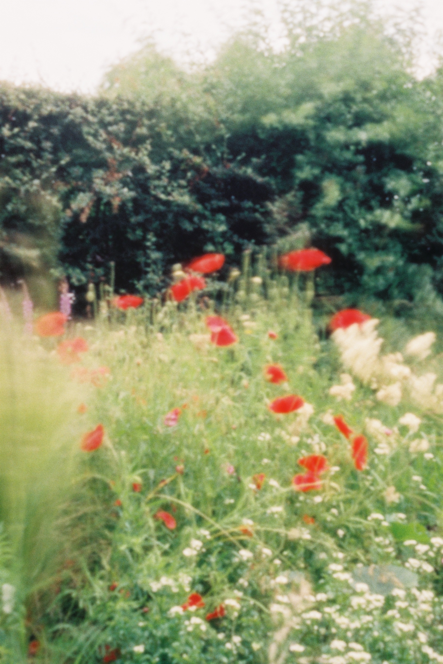
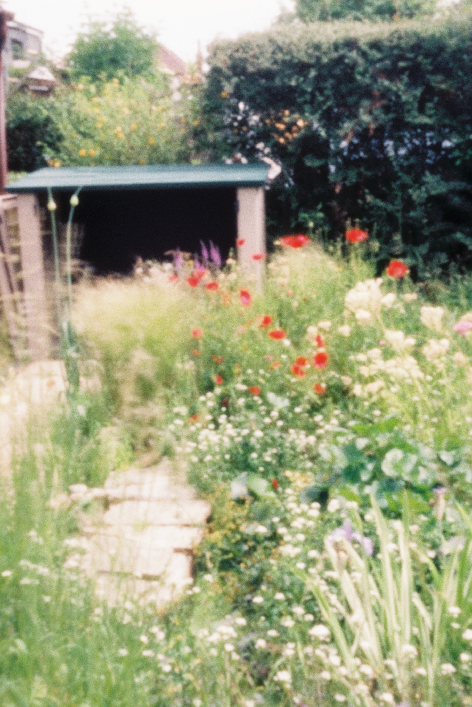
Are you an analogue photographer looking for a different way to present your images? Have you ever thought about shooting a sequence of stills and reanimating them in a zoetrope, an optical device from the Victorian era that pre-figured cinema? That is exactly what I decided to do as a project to occupy myself during the zombie apocalypse Covid-19 lockdown. Contact prints are aesthetically pleasing in themselves, and I wanted to tap into the history of the zoetrope by creating a movie-like continuous filmstrip of sequential images and bringing them to life.

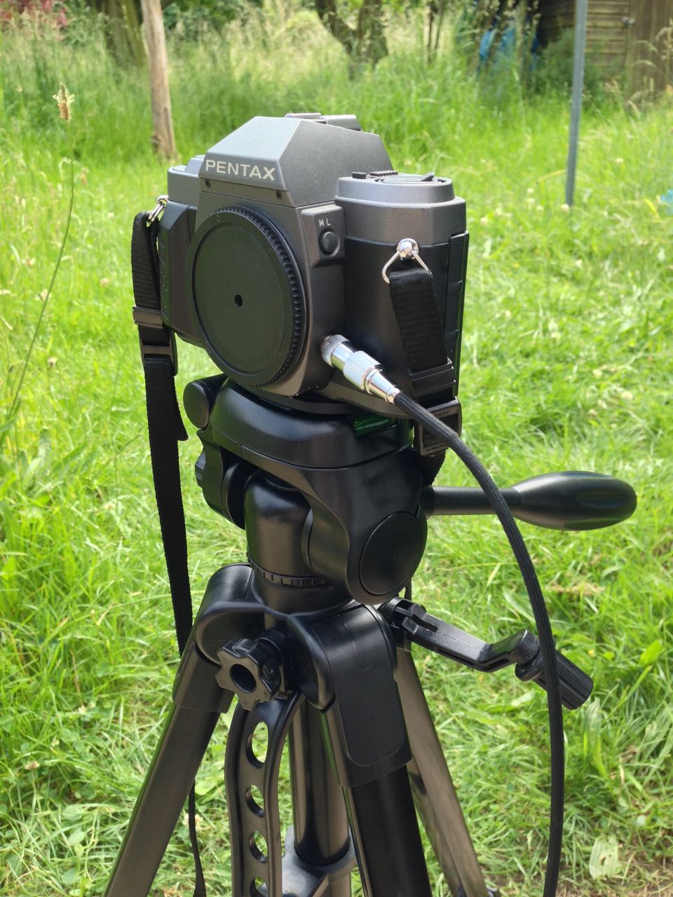
In the first part of my blog about this project, I covered the background and setting up a time-lapse of my cherry tree as content for the device. This weekend I shot the final image of the time-lapse, the last of the blossom having dropped. No-one stole my camera while it sat in my front garden for three weeks, and I was blessed with consistently sunny weather until the very last few days, when I was forced to adjust the exposure time to give me one or two extra stops. I’ll be interested to see how the images have come out, once I can get into the darkroom.

Meanwhile, I’ve been constructing the zoetrope itself, following this excellent article on Reframing Photography. Based on this, I’ve put together my own instructions specifically for making a device that holds 18 frames of contact-printed 35mm film. I chose a frame count of 18 for a few reasons:

  1. The resultant diameter, 220mm, seemed like a comfortable size, similar to a table lamp.
  2. Two image series of 18 frames fit neatly onto a 36 exposure film.
  3. Negatives are commonly cut into strips of six frames for storage and contact-printing, so a number divisible by six makes constructing the image loop a little more convenient.


You Will Need

  • Contact sheet containing 18 sequential 35mm images across three rows
  • A1 sheet of 300gsm card, ideally black
  • PVA glue
  • Ruler (the longer the better)
  • Set square
  • Compass
  • Pencil & eraser
  • Scissors
  • Craft knife or stanley knife
  • Paper clips or clothes pegs for clamping while glue dries
  • Rotating stand like a lazy susan or record player


Making the image loop

First, cut out the three rows of contact prints, leaving a bit of blank paper at one end of each row for overlap. Now glue them together into one long strip of 18 sequential images. The strip should measure 684mm plus overlap, because a 35mm negative or contact print measures 38mm in width including the border on one side: 38×18=684.

Glue the strip together into a loop with the images on the inside. This loop should have a diameter of 218mm. Note that we must make our zoetrope’s drum to a slightly bigger diameter, or the image loop won’t fit inside it. We’ll use our image loop to check the size of the drum; that’s why we’ve made it first. (If you don’t have your images ready yet, use an old contact sheet – as I did – or any strip of paper or light card of the correct size, 35mmx684mm.)


Making the side wall

Cut a strip of the black card measuring 723x90mm. This will be the side wall of your drum. Wrap this strip around your image loop, as tightly as you can without distorting the circular shape of the image loop. Mark where the card strip overlaps itself to find the circumference of the drum, which will be slightly bigger than the 684mm circumference of the image loop. In my case the drum circumference was 688mm – as illustrated in the diagram above. (You can click on it to enlarge it.)

Now we can measure and cut out the slots, one per image. Reframing Photography recommends a 1/8″ width, and initially I went with this, rounding it to 3mm. As with making a pinhole, a smaller slot means a sharper but darker image, while a bigger slot means a brighter but blurrier one. Once my zoetrope was complete, I felt that there was too much motion blur, so I retrofitted it with 1mm slots.

Let’s stick with 3x35mm (the same height as the images) for our slot size. How far apart should the slots be? They need to be evenly spaced around the circumference, so in my case 688÷18=38.2mm, i.e. a gap of 35.2mm between each slot and then 3mm for the slot itself. If your drum circumference is different to mine, you’ll have to do your own maths to work out the spacing.

(It was impossible to measure 38.2mm accurately, but I made a spreadsheet to give me values for the cumulative slot positions to the nearest millimetre: 38, 76, 115, 153, 191, 229, 268, 306, 344, 382, 420, 459, 497, 535, 573, 612, 650 and 688.)

Mark out your 18 slots, positioning them 15mm from the top of the side wall and 40mm from the bottom, then cut them out carefully using a knife and a ruler.

Now you can glue your side wall into a loop, using paper clips or clothes peg to hold it while the glue dries. I recommend double-checking your image loop fits inside beforehand. (Do not glue your image loop into the drum; this way you can swap it out for another image series whenever you like.)


Making the connector

The connector, as the name suggests, will connect the side wall to the base of the drum. (When I made a prototype, I tried skipping this stage, simply building the connecting teeth into the side wall, but this made it much harder to keep the drum a neat circle.)

Go back to your black card and cut another strip measuring 725x60mm. Score it all the way along the middle (i.e. 30mm from the edge) so that it can be folded in two, long-ways. Now cut triangular teeth into one half of the strip. Each triangle should have a 30mm base along the scored line.

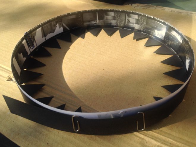
As with the side wall, you should check the circumference of the connector to ensure that it will fit around the side wall and image loop, and adjust it if necessary. My connector’s circumference, as shown on the diagram above, was 690mm.

Glue the strip into a loop, clamping it with clips or pegs while it dries. Again, it doesn’t hurt to double-check that it still fits around the side wall first.
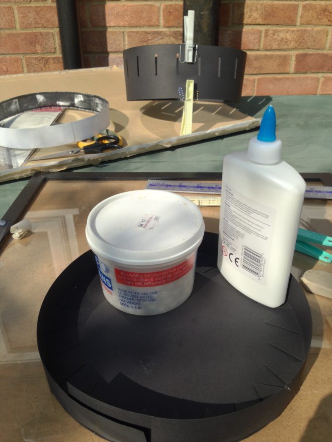
 

Making the base

Use a compass to draw a circle of 220mm in diameter on your remaining card, and cut it out. (If your connector is signficantly different in circumference to mine, divide that circumference by pi [3.14] to find the diameter that will work for you.)

Now you can glue the connector to the base. I suggest starting with a single tooth, putting a bottle of water or something heavy on it to keep it in place while it dries, then do the tooth directly opposite. Once that’s dry, do the ones at 90° and so on. This way you should prevent distortions creeping into the shape of the circle as you go around.

When that’s all dry, apply glue all around the inside of the upright section of the connector. Squish your side wall into a kidney bean shape to fit it inside the connector, then allow it to expand to its usual shape. If you have made it a tight enough fit, it will naturally press against the glue and the connector.
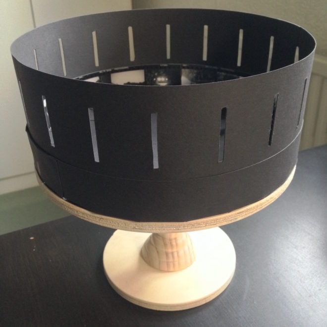
 

Making it Spin

The critical part of your zoetrope, the drum, is now complete. But to animate the images, you need to make it spin. There are a few ways you can do this:

  • Mount it on an old record player, making a hole in the centre of the base for the centre spindle.
  • Mount it on a rotating cake decoration stand or lazy susan.
  • Make your own custom stand.

I chose the latter, ordering some plywood discs cut to size, an unfinished candlestick and a lazy susan bearing, then assembling and varnishing them before gluing my drum to the top.

How to Make a Zoetrope for 35mm Contact Prints

Shooting a Time-lapse for a Zoetrope

Two years ago I made Stasis, a series of photographs that explored the confluence of time, space and light. Ever since then I’ve been meaning to follow it up with another photography project along similar lines, but haven’t got around to it. Well, with Covid-19 there’s not much excuse for not getting around to things any more.

Example of a zoetrope

So I’ve decided to make a zoetrope – a Victorian optical device which produces animation inside a spinning drum. The user looks through slits in the side of the drum to one of a series of images around the inside. When the drum is set spinning – usually by hand – the images appear to become one single moving picture. The slits passing rapidly through the user’s vision serve the same purpose as a shutter in a film projector, intermittently blanking out the image so that the persistence of vision effect kicks in.

Typically zoetropes contain drawn images, but they have been known to contain photographed images too. Eadward Muybridge, the father of cinema, reanimated some of his groundbreaking image series using zoetropes (though he favoured his proprietary zoopraxiscope) in the late nineteenth century. The device is thus rich with history and a direct antecedent of all movie projectors and the myriad devices capable of displaying moving images today.

This history, its relevance to my profession, and the looping nature of the animation all struck a chord with me. Stasis was to some extent about history repeating, so a zoetrope project seemed like it would sit well alongside it. Here though, history would repeat on a very small scale. Such a time loop, in which nothing can ever progress, feels very relevant under Covid-19 lockdown!

With that in mind, I decided that the first sequence I would shoot for the zoetrope would be a time-lapse of the cherry tree outside my window.  I chose a camera position at the opposite end of the garden, looking back at my window and front door – my lockdown “prison” – through the branches of the tree. (The tree was just about to start blooming.)

The plan is to shoot one exposure every day for at least the next 18 days, maybe more if necessary to capture the full life of the blossom. Ideally I want to record the blossom falling so that my sequence will loop neatly, although the emergence of leaves may interfere with that.

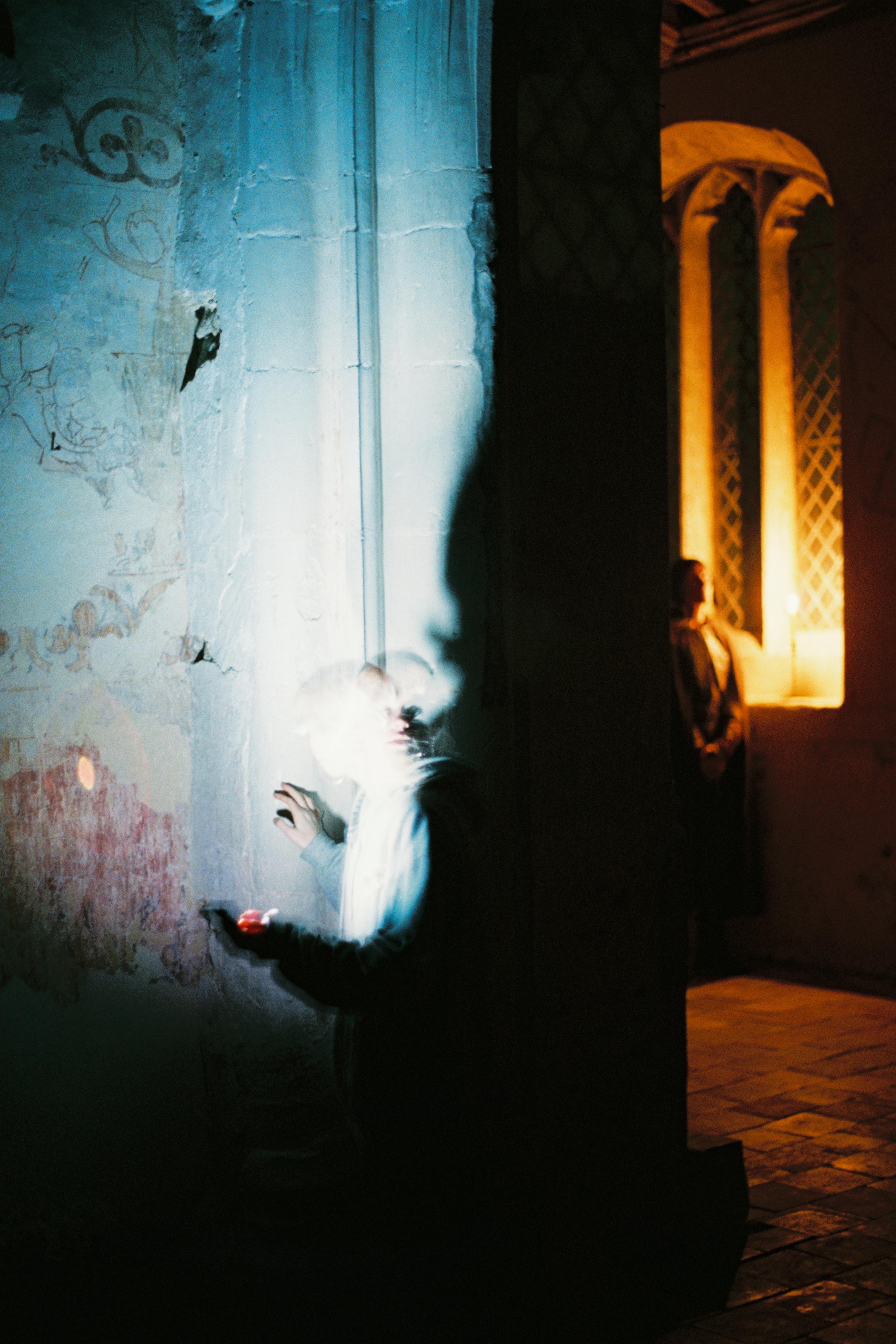
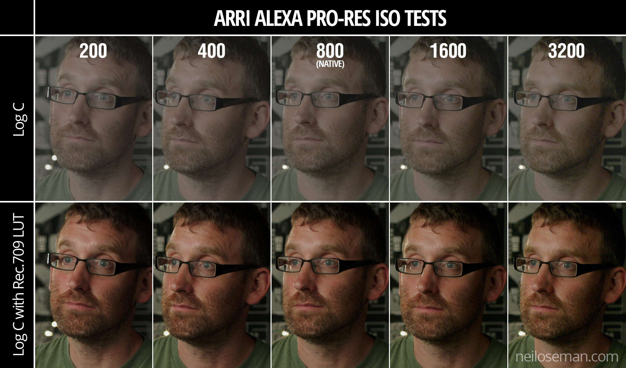
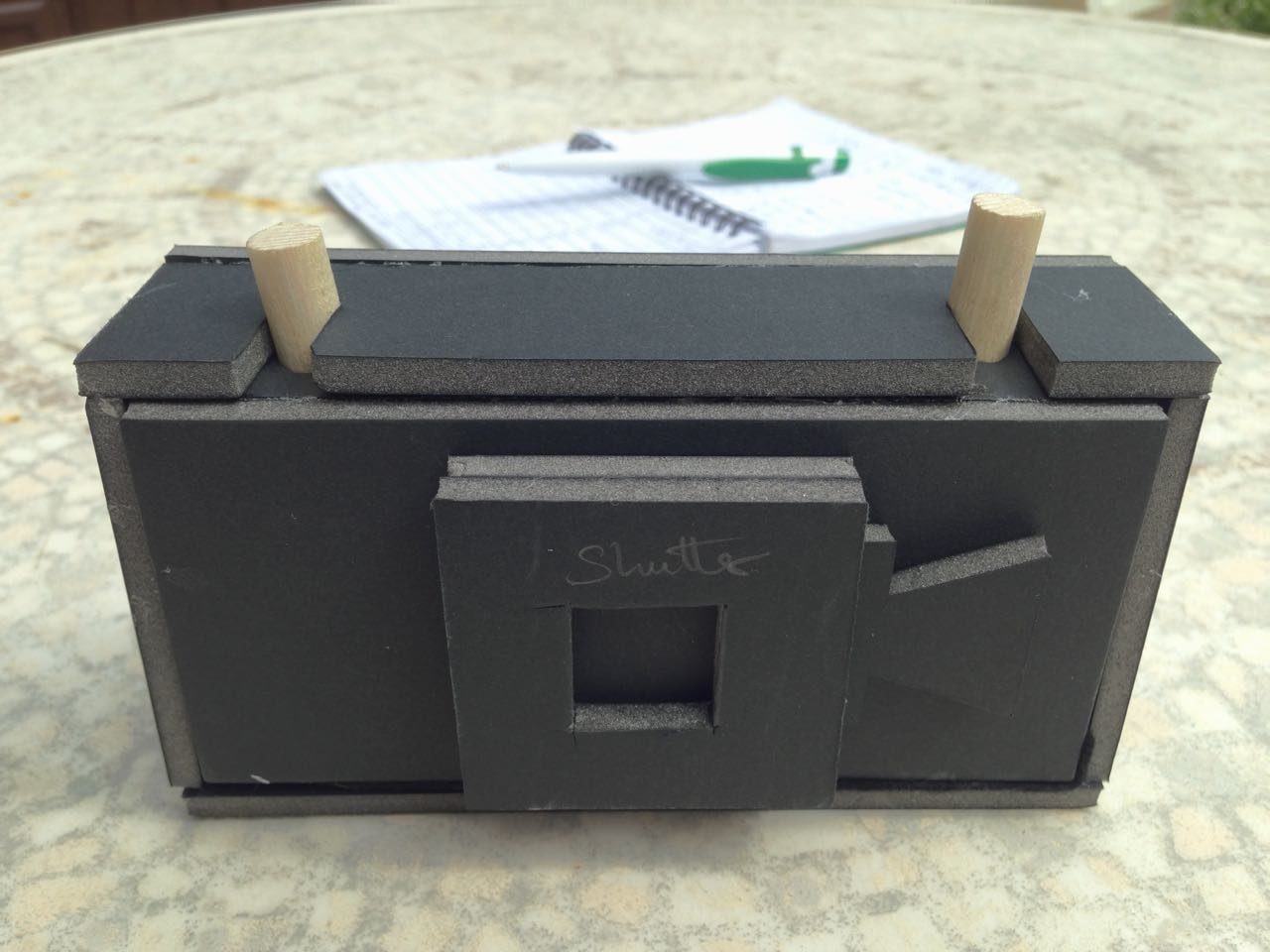
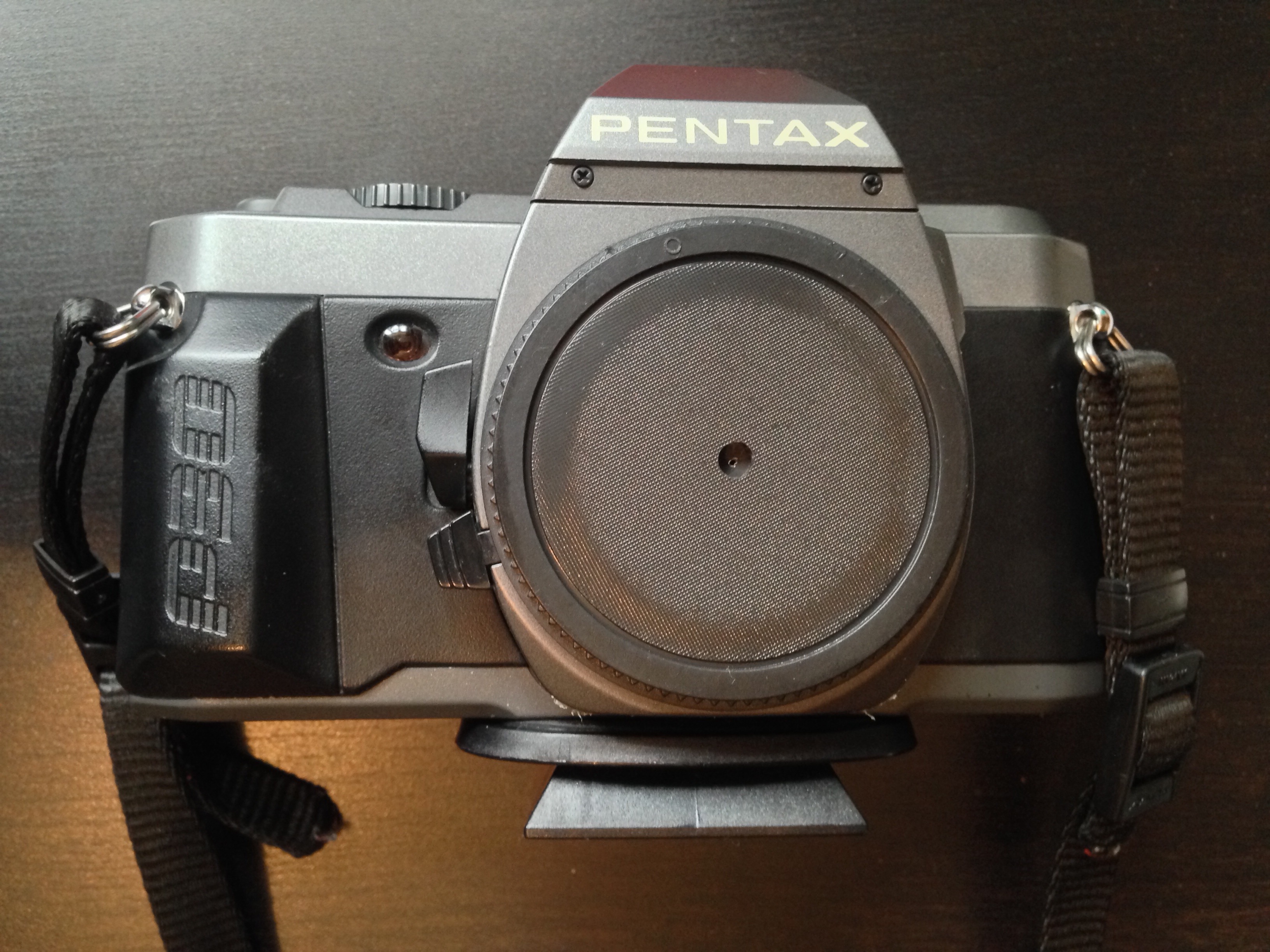
To make the whole thing a little more fun and primitive, I decided to shoot using the pinhole I made a couple of years ago. Since I plan to mount contact prints inside the zoetrope rather than enlargements, that’ll mean I’ve created and exhibited a motion picture without ever once putting the image through a lens.

I’m shooting on Ilford HP5+, a black-and-white stock with a published ISO of 400. My girlfriend bought me five roles for Christmas, which means I can potentially make ten 18-frame zoetrope inserts. I won’t be able to develop or print any of them until the lockdown ends, but that’s okay.

My first image was shot last Wednesday, a sunny day. The Sunny 16 rule tells me that at f/16 on a sunny day, my exposure should be equal to my ISO, i.e. 1/400th of a second for ISO 400. My pinhole has an aperture of f/365, which I calculated when I made it, so it’s about nine stops slower than f/16. Therefore I need to multiply that 1/400th of a second exposure time by two to the power of nine, which is 1.28 – call it one second for simplicity. ( I used my Sekonic incidence/reflectance meter to check the exposure, because it’s always wise to be sure when you haven’t got the fall-back of a digital monitor.)

One second is the longest exposure my Pentax P30t can shoot without switching to Bulb mode and timing it manually. It’s also about the longest exposure that HP5+ can do without the dreaded reciprocity failure kicking in. So all round, one second was a good exposure time to aim for.

The camera is facing roughly south, meaning that the tree is backlit and the wall of the house (which fills the background) is in shadow. This should make the tree stand out nicely. Every day may not be as sunny as today, so the light will inevitably change from frame to frame of the animation. I figured that maintaining a consistent exposure on the background wall would make the changes less jarring than trying to keep the tree’s exposure consistent.

I’ve been taking spot readings every day, and keeping the wall three-and-a-half stops under key, while the blossoms are about one stop over. I may well push the film – i.e. give it extra development time – if I end up with a lot of cloudy days where the blossoms are under key, but so far I’ve managed to catch the sun every time.

All this exposure stuff is great practice for the day when I finally get to shoot real motion picture film, should that day ever come, and it’s pretty useful for digital cinematography too.

Meanwhile, I’ve also made a rough prototype of the zoetrope itself, but more on that in a future post. Watch this space.

Shooting a Time-lapse for a Zoetrope

Pinhole Results

In my last couple of posts I described making and shooting with a pinhole attachment for my 35mm Pentax P30t SLR. Well, the scans are now back from the lab and I’m very pleased with them. They were shot on Fujifilm Superia Xtra 400.

As suspected, the 0.7mm pinhole was far too big, and the results are super-blurry:

See how contemptuous Spike is of this image. Or maybe that’s just Resting Cat Face.

The 0.125mm hole produced much better results, as you can see below. My f/stop calculations (f/365) seem to have been pretty close to the mark, although, as is often the case with film, the occasions where I gave it an extra stop of exposure produced even richer images. Exposure times for these varied between 2 and 16 seconds. Click to see them at higher resolution.

I love the ethereal, haunting quality of all these pictures, which recalls the fragility of Victorian photographs. It’s given me several ideas for new photography projects…

SaveSave

Pinhole Results

Adventures with a Pinhole

Last week I discussed making a pinhole for my Pentax 35mm SLR. Since then I’ve made a second pinhole and shot a roll of Fujifilm Superia X-tra 400 with them. Although I haven’t had the film processed yet, so the quality of the images is still a mystery, I’ve found shooting with a pinhole to be a really useful exercise.

My Pentax P30T fitted with a 0.125mm pinhole attachment


A Smaller Pinhole

Soon after my previous post, I went out into the back garden and took ten exposures of the pond and the neighbour’s cat with the 0.7mm pinhole. By that point I had decided that the hole was almost certainly too big. As I noted last week, Mr Pinhole gives an optimal diameter of 0.284mm for my camera. Besides that, the (incredibly dark) images in my viewfinder were very blurry, a sign that the hole needed to be smaller.

Scans of my two pinholes

So I peeled the piece of black wrap with the 0.7mm pinhole off my drilled body cap and replaced it with another hole measuring about 0.125mm. I had actually made this smaller hole first but rejected it because absolutely nothing was visible through the viewfinder, except for a bit of a blur in the centre. But now I came to accept that I would have to shoot blind if I wanted my images to be anything approaching sharp.

The 0.125mm(ish) pinhole magnified in Photoshop

I had made the 0.125mm hole by tapping the black wrap with only the very tip of the needle, rather than pushing it fully through. Prior to taping it into the body cap, I scanned it at high resolution and measured it using Photoshop. This revealed that it’s a very irregular shape, which probably means the images will still be pretty soft. Unfortunately I couldn’t see a way of getting it any more circular; sanding didn’t seem to help.

Again I found the f-stop of the pinhole by dividing the flange focal distance (45.65mm) by the hole diameter, the result being about f/365. My incident-light meter only goes up to f/90, so I needed to figure out how many stops away from f/365 that is. I’m used to working in the f/1.4-f/22 range, so I wasn’t familiar with how the stop series progresses above f/90. Turns out that you can just multiply by 1.4 to roughly find the next stop up, so after f/90 it’s 128, then 180, then 256, then 358, pretty close to my f/365 pinhole. So whatever reading my meter gave me for f/90, I knew that I would need to add 4 stops of exposure, i.e. multiply the shutter interval by 16. (Stops are a base 2 logarithmic scale. See my article on f-stops, T-stops and ND filters for more info.)


The Freedom of Pinhole Shooting

I’ve just spent a pleasant hour or so in the garden shooting the remaining 26 exposures on my roll with the new 0.125mm pinhole. Regardless of how the photos come out, I found it a fun and fascinating exercise.

Knowing that the images would be soft made me concentrate on colour and form far more than I normally would. Not being able to frame using the viewfinder forced me to visualise the composition mentally. And as someone who finds traditional SLRs very tricky to focus, it was incredibly freeing not to have to worry about that, not to have to squint through the viewfinder at all, but just plonk the camera down where it looked right and squeeze the shutter.

Of course, before squeezing the shutter I needed to take incident-light readings, because the TTL (through the lens) meter was doing nothing but flash “underexposed” at me. Being able to rely solely on an incident meter to judge exposure is a very useful skill for a DP, so this was great practice. I’ve been reading a lot about Ansel Adams and the Zone System lately, and although this requires a spot reflectance meter to be implemented properly, I tried to follow Adams’ philosophy, visualising how I wanted the subject’s tones to correspond to the eventual print tones. (Expect an article about the Zone System in the not-too-distant future!)


D.I.Y. pinhole Camera

On Tuesday night I went along to a meeting of Cambridge Darkroom, the local camera club. By coincidence, this month’s subject was pinhole cameras. Using online plans, Rich Etteridge had made up kits for us to construct our own complete pinhole cameras in groups. I teamed up with a philosophy student called Tim, and we glued a contraption together in the finest Blue Peter style. The actual pinholes were made in metal squares cut from Foster’s cans, which are apparently something Rich has in abundance.

DIY pinhole camera

I have to be honest though: I’m quite scared of trying to use it. Look at those dowels. Can I really see any outcome of attempting to load this camera other than a heap of fogged film on the floor? No. I think I’ll stick with my actual professionally-made camera body for now. If the pinhole photos I took with that come out alright, then maaaaaaybe I’ll consider lowering the tech level further and trying out my Blue Peter camera. Either way, big thanks to Rich for taking all that time to produce the kits and talk us through the construction.

Watch this space to find out how my pinhole images come out.

SaveSave

Adventures with a Pinhole

Making a Pinhole Attachment for an SLR

Last autumn, after a few years away from it, I got back into 35mm stills photography. I’ve been reading a lot of books about photography: the art of it, the science and the history too. I’ve even taken a darkroom course to learn how to process and print my own black and white photos.

Shooting stills in my spare time gives me more opportunities to develop my eye for composition, my exposure-judging skills and my appreciation of natural light. Beyond that, I’ve discovered interesting parallels between electronic and photochemical imaging which enhance my understanding of both.

For example, I used to think of changing the ISO on a digital camera as analogous to loading a different film stock into a traditional camera. However, I’ve come to realise it’s more like changing the development time – it’s an after-the-fact adjustment to an already-captured (latent) image. There’s more detail on this analogy in my ISO article at Red Shark News.

The importance of rating an entire roll of film at the same exposure index, as it must all be developed for the same length of time, also has resonance in the digital world. Maintaining a consistency of exposure (or the same LUT) throughout a scene or sequence is important in digital filmmaking because it makes the dailies more watchable and reduces the amount of micro-correction which the colourist has to do down the line.

Anyway, this is all a roundabout way of explaining why I decided to make a pinhole attachment for my SLR this week. It’s partly curiosity, partly to increase my understanding of image-making from first principles.

The pinhole camera is the simplest image-making device possible. Because light rays travel in straight lines, when they pass through a very small hole they emerge from the opposite side in exactly the same arrangement, only upside-down, and thus form an image on a flat surface on the other side. Make that flat surface a sheet of film or a digital sensor and you can capture this image.


How to make a pinhole attachment

I used Experimental Filmmaking: Break the Machine by Kathryn Ramey as my guide, but it’s really pretty straightforward.

You will need:

  • an extra body cap for your camera,
  • a drill,
  • a small piece of smooth, non-crumpled black wrap, or kitchen foil painted black,
  • scissors,
  • gaffer tape (of course), and
  • a needle or pin.

Instructions:

  1. Drill a hole in the centre of the body cap. The size of the hole is unimportant.
  2. Use the pin or needle to pierce a hole in the black wrap, at least a couple of centimetres from the edge.
  3. Cut out a rough circle of the black wrap, with the pinhole in the middle. This circle needs to fit on the inside of the body cap, with the pinhole in the centre of the drilled hole.
  4. Use the gaffer tape to fix the black wrap tightly to the inside of the body cap.
  5. Fit the body cap to your camera.

The smaller the pinhole is, the sharper the image will be, but the darker too. The first pinhole I made was about 0.1-0.2mm in diameter, but when I fitted it to my camera and looked through the viewfinder I could hardly make anything out at all. So I made a second one, this time pushing the pin properly through the black wrap, rather than just pricking it with the tip. (Minds out of the gutter, please.) The new hole was about 0.7mm but still produced an incredibly dark image in the viewfinder.


Exposing a pinhole image

If you’re using a digital camera, you can of course judge your exposure off the live-view screen. Things are a little more complicated if, like me, you’re shooting on film.

In theory the TTL (through the lens) light meter should give me just as reliable a reading as it would with a lens. The problem is that, even with the shutter set to 1 second, and ISO 400 Fujifilm Super X-tra loaded, the meter tells me I’m underexposed. Admittedly the weather has been overcast since I made the pinhole yesterday, so I may get a useful reading when the sun decides to come out again.

Failing that, I can use my handheld incident-light meter to determine the exposure…. once I’ve worked out what the f-stop of my pinhole is.

As I described in my article on aperture settings, the definition of an f-stop is: the ratio of the focal length to the aperture diameter. We’re all used to using lenses that have a clearly defined and marked focal length, but what is the focal length in a pinhole system?

The definition of focal length is the distance between the point where the light rays focus (i.e. converge to a point) and the image plane. So the focal length of a pinhole camera is very simply the distance from the pinhole itself to the film or digital sensor. Since my pinhole is more or less level with the top of the lens mount, the focal length is going to be approximately equal to the camera’s flange focal distance (defined as the distance between the lens mount and the image plane). According to Wikipedia, the flange focal distance for a Pentax K-mount camera is 45.46mm.

So the f-stop of my 0.7mm pinhole is f/64, because 45.64 ÷ 0.7 ≈ 64. Conveniently, f/64 is the highest stop my light meter will handle.

The website Mr Pinhole has a calculator to help you figure this sort of stuff out, and it even tells you the optimal pinhole diameter for your focal length. Apparently this is 0.284mm in my case, so my images are likely to be quite soft.

Anyway, when the sun comes out I’ll take some pictures and let you know how I get on!

Making a Pinhole Attachment for an SLR

How Big a Light do I Need?

Experience goes a long way, but sometimes you need to be more precise about what size of lighting instruments are required for a particular scene. Night exteriors, for example; you don’t want to find out on the day that the HMI you hired as your “moon” backlight isn’t powerful enough to cover the whole of the car park you’re shooting in. How can you prep correctly so that you don’t get egg on your face?

There are two steps: 1. determine the intensity of light you require on the subject, and 2. find a combination of light fixture and fixture-to-subject distance that will provide that intensity.


The Required intensity

The goal here is to arrive at a number of foot-candles (fc). Foot-candles are a unit of light intensity, sometimes more formally called illuminance, and one foot-candle is the illuminance produced by a standard candle one foot away. (Illuminance can also be measured in the SI unit of lux, where 1 fc ≈ 10 lux, but in cinematography foot-candles are more commonly used. It’s important to remember that illuminance is a measure of the light incident to a surface, i.e. the amount of light reaching the subject. It is not to be confused with luminance, which is the amount of light reflected from a surface, or with luminous power, a.k.a. luminous flux, which is the total amount of light emitted from a source.)

Usually you start with a T-stop (or f-stop) that you want to shoot at, based on the depth of field you’d like. You also need to know the ISO and shutter interval (usually 1/48th or 1/50th of a second) you’ll be shooting at. Next you need to convert these facets of exposure into an illuminance value, and there are a few different ways of doing this.

One method is to use a light meter, if you have one, which you enter the ISO and shutter values into. Then you wave it around your office, living room or wherever, pressing the trigger until you happen upon a reading which matches your target f-stop. Then you simply switch your meter into foot-candles mode and read off the number. This method can be a bit of a pain in the neck, especially if – like mine – your meter requires fiddly flipping of dip-switches and additional calculations to get a foot-candles reading out of.

A much simpler method is to consult an exposure table, like the one below, or an exposure calculator, which I’m sure is a thing which must exist, but I’ll be damned if I could find one.

Some cinematographers memorise the fact that 100fc is f/2.8 at ISO 100, and work out other values from that. For example, ISO 400 is four times (two stops) faster than ISO 100, so a quarter of the light is required, i.e. 25fc.

Alternatively, you can use the underlying maths of the above methods. This is unlikely to be necessary in the real world, but for the purposes of this blog it’s instructive to go through the process. The equation is:

where

  • b is the illuminance in fc,
  • f is the f– or T-stop,
  • s is the shutter interval in seconds, and
  • i is the ISO.

Say I’m shooting on an Alexa with a Cooke S4 Mini lens. If I have the lens wide open at T2.8, the camera at its native ISO of 800 and the shutter interval at the UK standard of 1/50th (0.02) of a second…

… so I need about 12fc of light.


The right instrument

In the rare event that you’re actually lighting your set with candles – as covered in my Barry Lyndon and Stasis posts – then an illuminance value in fc is all you need. In every other situation, though, you need to figure out which electric light fixtures are going to give you the illuminance you need.

Manufacturers of professional lighting instruments make this quite easy for you, as they all provide data on the illuminance supplied by their products at various distances. For example, if I visit Mole Richardson’s webpage for their 1K Baby-Baby fresnel, I can click on the Performance Data table to see that this fixture will give me the 12fc (in fact slightly more, 15fc) that I required in my Alexa/Cooke example at a distance of 30ft on full flood.

Other manufacturers provide interactive calculators: on ETC’s site you can drag a virtual Source Four back and forth and watch the illuminance read-out change, while Arri offers a free iOS/Android app with similar functionality.

If you need to calculate an illuminance value for a distance not specified by the manufacturer, you can derive it from distances they do specify, by using the Inverse Square Law. However, as I found in my investigatory post about the law, that could be a whole can of worms.

If illuminance data is not available for your light source, then I’m afraid more maths is involved. For example, the room I’m currently in is lit by a bulb that came in a box marked “1,650 lumens”, which is the luminous power. One lumen is one foot-candle per square foot. To find out the illuminance, i.e. how many square feet those lumens are spread over, we imagine those square feet as the area of a sphere with the lamp at the centre, and where the radius r is the distance from the lamp to the subject. So:

where

  • is again the illuminance in fc,
  • is the luminous power of the souce in lumens, and
  • r is the lamp-to-subject distance in feet.

(I apologise for the mix of Imperial and SI units, but this is the reality in the semi-Americanised world of British film production! Also, please note that this equation is for point sources, rather than beams of light like you get from most professional fixtures. See this article on LED Watcher if you really want to get into the detail of that.)

So if I want to shoot that 12fc scene on my Alexa and Cooke S4 Mini under my 1,650 lumen domestic bulb…

… my subject needs to be 3’4″ from the lamp. I whipped out my light meter to check this, and it gave me the target T2.8 at 3’1″ – pretty close!


Do I have enough light?

If you’re on a tight budget, it may be less a case of, “What T-stop would I like to shoot at, and what fixture does that require?” and more a case of, “Is the fixture which I can afford bright enough?”

Let’s take a real example from Perplexed Music, a short film I lensed last year. We were shooting on an Alexa at ISO 1600, 1/50th sec shutter, and on Arri/Zeiss Ultra Primes, which have a maximum aperture of T1.9. The largest fixture we had was a 2.5K HMI, and I wanted to be sure that we would have enough light for a couple of night exteriors at a house location.

In reality I turned to an exposure table to find the necessary illuminance, but let’s do the maths using the first equation that we met in this post:

Loading up Arri’s photometrics app, I could see that 2.8fc wasn’t going to be a problem at all, with the 2.5K providing 5fc at the app’s maximum distance of 164ft.

That’s enough for today. All that maths may seem bewildering, but most of it is eliminated by apps and other online calculators in most scenarios, and it’s definitely worth going to the trouble of checking you have enough light before you’re on set with everyone ready to roll!

See also: 6 Ways of Judging Exposure

SaveSave

SaveSave

How Big a Light do I Need?

6 Ways to Judge Exposure

Exposing the image correctly is one of the most important parts of a cinematographer’s job. Choosing the T-stop can be a complex technical and creative decision, but fortunately there are many ways we can measure light to inform that decision.

First, let’s remind ourselves of the journey light makes: photons are emitted from a source, they strike a surface which absorbs some and reflects others – creating the impressions of colour and shade; then if the reflected light reaches an eye or camera lens it forms an image. We’ll look at the various ways of measuring light in the order the measurements occur along this light path, which is also roughly the order in which these measurements are typically used by a director of photography.


1. Photometrics data

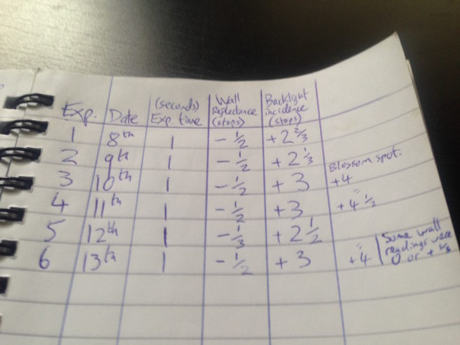
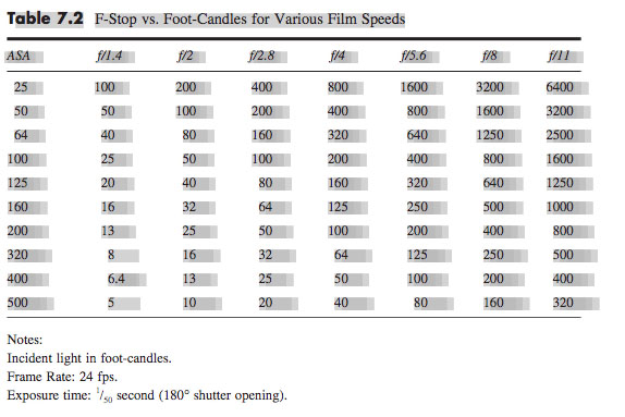
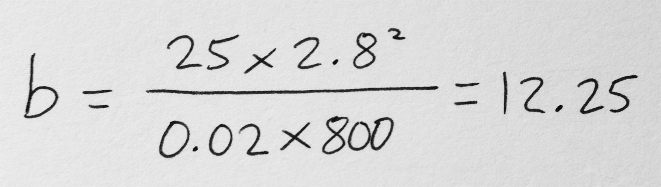
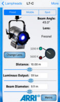
You can use data supplied by the lamp manufacturer to calculate the exposure it will provide, which is very useful in preproduction when deciding what size of lamps you need to hire. There are apps for this, such as the Arri Photometrics App, which allows you to choose one of their fixtures, specify its spot/flood setting and distance from the subject, and then tells you the resulting light level in lux or foot-candles. An exposure table or exposure calculation app will translate that number into a T-stop at any given ISO and shutter interval.


2. Incident meter

Some believe that light meters are unnecessary in today’s digital landscape, but I disagree. Most of the methods listed below require the camera, but the camera may not always be handy – on a location recce, for example. Or during production, it would be inconvenient to interrupt the ACs while they’re rigging the camera onto a crane or Steadicam. This is when having a light meter on your belt becomes very useful.

An incident meter is designed to measure the amount of light reaching the subject. It is recognisable by its white dome, which diffuses and averages the light striking its sensor. Typically it is used to measure the key, fill and backlight levels falling on the talent. Once you have input your ISO and shutter interval, you hold the incident meter next to the actor’s face (or ask them to step aside!) and point it at each source in turn, shading the dome from the other sources with your free hand. You can then decide if you’re happy with the contrast ratios between the sources, and set your lens to the T-stop indicated by the key-light reading, to ensure correct exposure of the subject’s face.


3. Spot meter (a.k.a. reflectance meter)

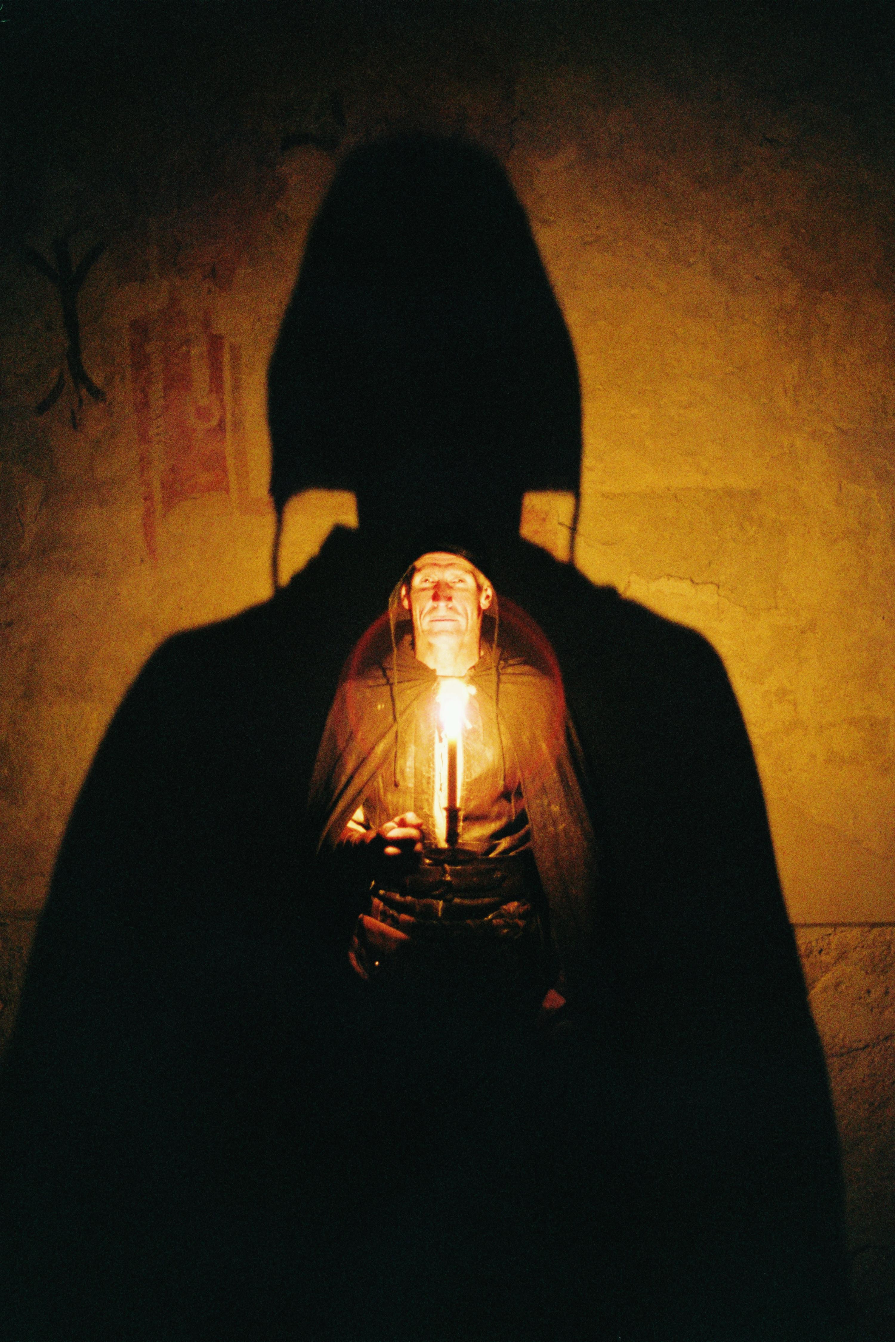
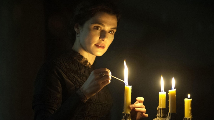
Now we move along the light path and consider light after it has been reflected off the subject. This is what a spot meter measures. It has a viewfinder with which you target the area you want to read, and it is capable of metering things that would be impractical or impossible to measure with an incident meter. If you had a bright hillside in the background of your shot, you would need to drive over to that hill and climb it to measure the incident light; with a spot meter you would simply stand at the camera position and point it in the right direction. A spot meter can also be used to measure light sources themselves: the sky, a practical lamp, a flame and so on.

But there are disadvantages too. If you spot meter a Caucasian face, you will get a stop that results in underexposure, because a Caucasian face reflects quite a lot of light. Conversely, if you spot meter an African face, you will get a stop that results in overexposure, because an African face reflects relatively little light. For this reason a spot meter is most commonly used to check whether areas of the frame other than the subject – a patch of sunlight in the background, for example – will blow out.

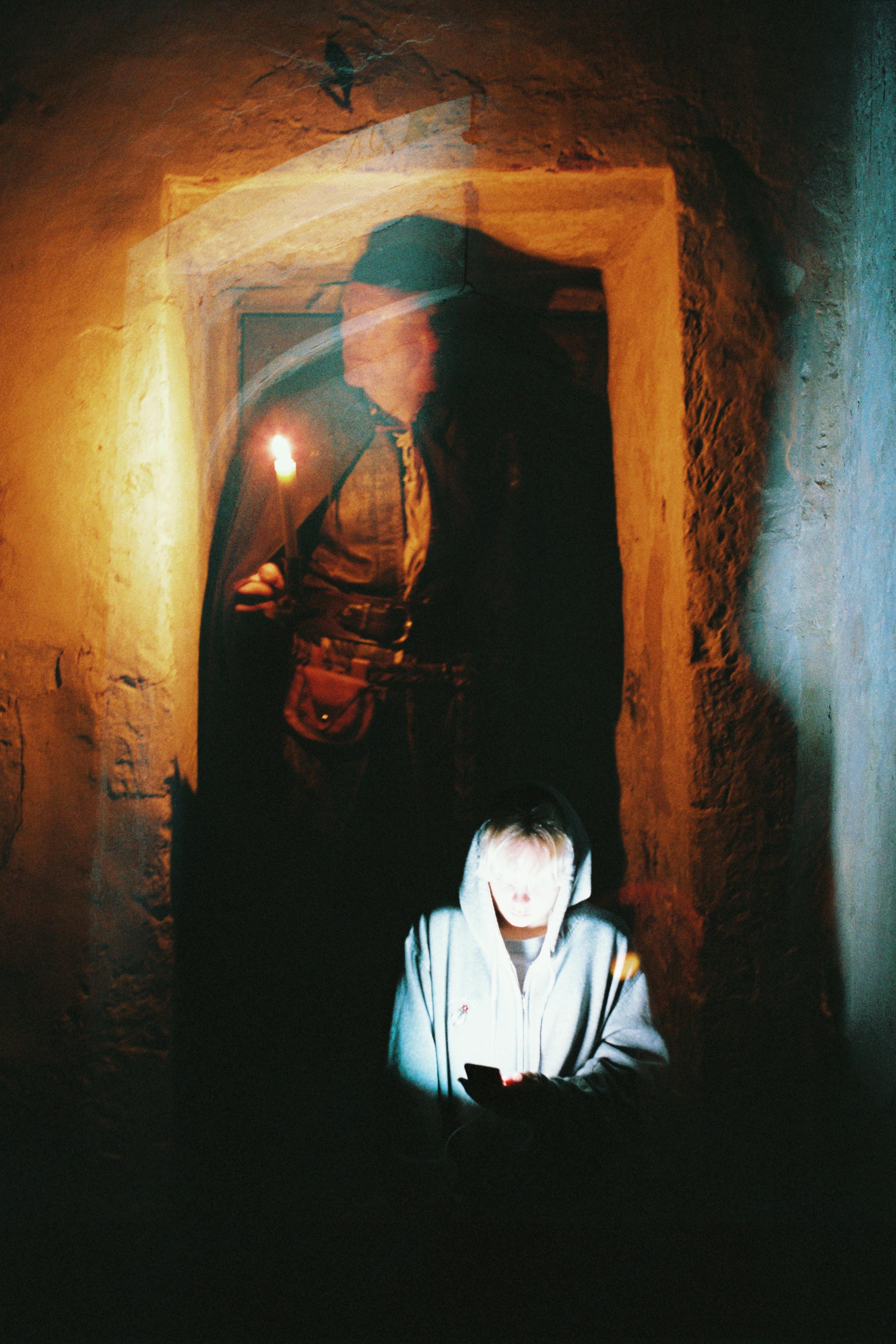
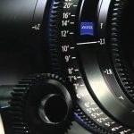
Your smartphone can be turned into a spot meter with a suitable app, such as Cine Meter II, though you will need to configure it using a traditional meter and a grey card. With the addition of a Luxiball attachment for your phone’s camera, it can also become an incident meter.

The remaining three methods of judging exposure which I will cover all use the camera’s sensor itself to measure the light. Therefore they take into account any filters you’re using as well transmission loss within the lens (which can be an issue when shooting on stills glass, where the marked f-stops don’t factor in transmission loss).


4. Monitors and viewfinders

The letter. Photo: Amy Nicholson

In the world of digital image capture, it can be argued that the simplest and best way to judge exposure is to just observe the picture on the monitor. The problem is, not all screens are equal. Cheap monitors can misrepresent the image in all kinds of ways, and even a high-end OLED can deceive you, displaying shadows blacker than any cinema or home entertainment system will ever match. There are only really two scenarios in which you can reliably judge exposure from the image itself: if you’ve owned a camera for a while and you’ve become very familiar with how the images in the viewfinder relate to the finished product; or if the monitor has been properly calibrated by a DIT (Digital Imaging Technician) and the screen is shielded from light.

Most cameras and monitors have built-in tools which graphically represent the luminance of the image in a much more accurate way, and we’ll look at those next. Beware that if you’re monitoring a log or RAW image in Rec.709, these tools will usually take their data from the Rec.709 image.


5. Waveforms and histograms

These are graphs which show the prevalence of different tones within the frame. Histograms are the simplest and most common. In a histogram, the horizontal axis represents luminance and the vertical axis shows the number of pixels which have that luminance. It makes it easy to see at a glance whether you’re capturing the greatest possible amount of detail, making best use of the dynamic range. A “properly” exposed image, with a full range of tones, should show an even distribution across the width of the graph, with nothing hitting the two sides, which would indicate clipped shadows and highlights. A night exterior would have a histogram crowded towards the left (darker) side, whereas a bright, low contrast scene would be crowded on the right.

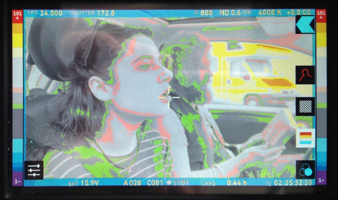
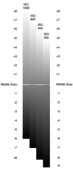
A waveform plots luminance on the vertical axis, with the horizontal axis matching the horizontal position of those luminance values within the frame. The density of the plotting reveals the prevalence of the values. A waveform that was dense in the bottom left, for example, would indicate a lot of dark tones on the lefthand side of frame. Since the vertical (luminance) axis represents IRE (Institute of Radio Engineers) values, waveforms are ideal when you need to expose to a given IRE, for example when calibrating a system by shooting a grey card. Another common example would be a visual effects supervisor requesting that a green screen be lit to 50 IRE.


6. Zebras and false colours

Almost all cameras have zebras, a setting which superimposes diagonal stripes on parts of the image which are over a certain IRE, or within a certain range of IREs. By digging into the menus you can find and adjust what those IRE levels are. Typically zebras are used to flag up highlights which are clipping (theoretically 100 IRE), or close to clipping.

Exposing an image correctly is not just about controlling highlight clipping however, it’s about balancing the whole range of tones – which brings us to false colours. A false colour overlay looks a little like a weather forecaster’s temperature map, with a code of colours assigned to various luminance values. Clipped highlights are typically red, while bright areas still retaining detail (known as the “knee” or “shoulder”) are yellow. Middle grey is often represented by green, while pink indicates the ideal level for caucasian skin tones (usually around 55 IRE). At the bottom end of the scale, blue represents the “toe” – the darkest area that still has detail – while purple is underexposed. The advantage of zebras and false colours over waveforms and histograms is that the former two show you exactly where the problem areas are in the frame.

I hope this article has given you a useful overview of the tools available for judging exposure. Some DPs have a single tool they rely on at all times, but many will use all of these methods at one time or another to produce an image that balances maximising detail with creative intent. I’ll leave you with a quote from the late, great Douglas Slocombe, BSC who ultimately used none of the above six methods!

I used to use a light meter – I used one for years. Through the years I found that, as schedules got tighter and tighter, I had less and less time to light a set. I found myself not checking the meter until I had finished the set and decided on the proper stop. It would usually say exactly what I thought it should. If it didn’t, I wouldn’t believe it, or I would hold it in such a way as to make it say my stop. After a time I decided this was ridiculous and stopped using it entirely. The “Raiders” pictures were all shot without a meter. I just got used to using my eyes.

6 Ways to Judge Exposure

Creating “Stasis”

Stasis is a personal photography project about time and light. You can view all the images here, and in this post I’ll take you through the technical and creative process of making them.

I got into cinematography directly through a love of movies and filmmaking, rather than from a fine art background. To plug this gap, over the past few of years I’ve been trying to give myself an education in art by going to galleries, and reading art and photography books. I’ve previously written about how JMW Turner’s work captured my imagination, but another artist whose work stood out to me was Gerrit (a.k.a. Gerard) Dou. Whereas most of the Dutch 17th century masters painted daylight scenes, Dou often portrayed people lit by only a single candle.

“A Girl Watering Plants” by Gerrit Dou

At around the same time as I discovered Dou, I researched and wrote a blog post about Barry Lyndon‘s groundbreaking candlelit scenes. This got me fascinated by the idea that you can correctly expose an image without once looking at a light meter or digital monitor, because tables exist giving the appropriate stop, shutter and ISO for any given light level… as measured in foot-candles. (One foot-candle is the amount of light received from a standard candle that is one foot away.)

So when I bought a 35mm SLR (a Pentax P30T) last autumn, my first thought was to recreate some of Dou’s scenes. It would be primarily an exercise in exposure discipline, training me to judge light levels and fall-off without recourse to false colours, histograms or any of the other tools available to a modern DP.

I conducted tests with Kate Madison, who had also agreed to furnish period props and costumes from the large collection which she had built up while making Born of Hope and Ren: The Girl with the Mark. Both the tests and the final images were captured on Fujifilm Superia X-tra 400. Ideally I would have tested multiple stocks, but I must confess that the costs of buying and processing several rolls were off-putting. I’d previously shot some basic latitude tests with Superia, so I had some confidence about what it could and couldn’t do. (It can be over-exposed at least five stops and still look good, but more than a stop under and it falls apart.) I therefore confined myself to experimenting with candle-to-subject distances, exposure times and filtration.

The tests showed that the concept was going to work, and also confirmed that I would need to use an 80B filter to cool the “white balance” of the film from its native daylight to tungsten (3400K). (As far as I can tell, tungsten-balanced stills film is no longer on the market.) Candlelight has a colour temperature of about 1800K, so it still reads as orange through an 80B, but without the filter it’s an ugly red.

Meanwhile, the concept had developed beyond simply recreating Gerrit Dou’s scenes. I decided to add a second character, contrasting the historical man lit only by his candle with a modern girl lit only by her phone. Flames have a hypnotic power, tapping into our ancient attraction to light, and today’s smartphones have a similarly powerful draw.

The candlelight was 1600K warmer than the filtered film, so I used an app called Colour Temp to set my iPhone to 5000K, making it 1600K cooler than the film; the phone would therefore look as blue as the candle looked orange. (Unfortunately my phone died quickly and I had trouble recharging it, so some of the last shots were done with Izzi’s non-white-balanced phone.) To match the respective colours of light, we dressed Ivan in earthy browns and Izzi in blues and greys.

Artemis recce image

We shot in St. John’s Church in Duxford, Cambridgeshire, which hasn’t been used as a place of worship since the mid-1800s. Unique markings, paintings and graffiti from the middle ages up to the present give it simultaneously a history and a timelessness, making it a perfect match to the clash of eras represented by my two characters. It resonated with the feelings I’d had when I started learning about art and realised the continuity of techniques and aims from me in my cinematography back through time via all the great artists of the past to the earliest cave paintings.

I knew from the tests that long exposures would be needed. Extrapolating from the exposure table, one foot-candle would require a 1/8th of a second shutter with my f1.4 lens wide open and the Fujifilm’s ISO of 400. The 80B has a filter factor of three, meaning you need three times more light, or, to put it another way, it cuts 1 and 2/3rds of a stop. Accounting for this, and the fact that the candle would often be more than a foot away, or that I’d want to see further into the shadows, the exposures were all at least a second long.

As time had become very much the theme of the project, I decided to make the most of these long exposures by playing with motion blur. Not only does this allow a static image – paradoxically – to show a passage of time, but it recalls 19th century photography, when faces would often blur during the long exposures required by early emulsions. Thus the history of photography itself now played a part in this time-fluid project.

I decided to shoot everything in portrait, to make it as different as possible from my cinematography work. Heavily inspired by all the classical art I’d been discovering, I used eye-level framing, often flat-on and framed architecturally with generous headroom, and a normal lens (an Asahi SMC Pentax-M 50mm/f1.4) to provide a natural field of view.

I ended up using my light meter quite a lot, though not necessarily exposing as it indicated. It was all educated guesswork, based on what the meter said and the tests I’d conducted.

I was tempted more than once to tell a definite story with the images, and had to remind myself that I was not making a movie. In the end I opted for a very vague story which can be interpreted many ways. Which of the two characters is the ghost? Or is it both of them? Are we all just ghosts, as transient as motion blur? Do we unwittingly leave an intangible imprint on the universe, like the trails of light my characters produce, or must we consciously carve our mark upon the world, as Ivan does on the wall?

Models: Izzi Godley & Ivan Moy. Stylist: Kate Madison. Assistant: Ash Maharaj. Location courtesy of the Churches Conservation Trust. Film processing and scanning by Aperture, London.

Creating “Stasis”

Alexa ProRes ISO Tests

My Cousin Rachel

I’ve shot three features on Arri Alexas, but I’ve never moved the ISO away from its native setting of 800 for fear of noise and general image degradation. Recently I read an article about the cinematography of My Cousin Rachel, in which DP Mike Eley mentioned shooting the night scenes at ISO 1600. I deliberately set off for the cinema in order to analyse the image quality of this ISO on the big screen. Undoubtedly I’ve unwittingly seen many things that were shot on an Alexa at ISO 1600 over the past few years, but this was the first time I’d given it any real thought.

To my eye, My Cousin Rachel looked great. So when I was at Arri Rental the other week testing some lenses, I decided to shoot a quick ISO test to see exactly what would happen when I moved away from the native 800.

But before we get to the test footage, for those of you unsure exactly what ISO is, here’s an introduction. The more experienced amongst you may wish to skip down to the video and analysis.


What is ISO?

A revised and updated version of this section is available.

ISO is a measure of a camera’s light sensitivity; the higher the ISO, the less light it requires to expose an image.

The acronym actually stands for International Organization for Standardization [sic], the body which in 1974 combined the old ASA (American Standards Association) units of film speed with the German DIN standard. That’s why you’ll often hear the terms ISO and ASA used interchangeably. On some cameras, like the Alexa, you’ll see it called EI (Exposure Index) in the menus.

A common ISO to shoot at today is 800. One way of defining ISO 800 is that it’s the sensitivity required to correctly expose a key-light of 3 foot-candles with a lens of T-stop 1.4 and a 180° shutter at 24fps, as we saw in my Barry Lyndon blog.

If we double the ISO we double the effective sensitivity of the camera, or halve the amount of light it requires. So at ISO 1600 we would only need 1.5 foot-candles of light (all the other settings being the same), and at ISO 3200 we would need just 0.75 foot-candles. Conversely, at ISO 400 we would need 6 foot-candles, or 12 at ISO 200. Check out this exposure chart if it’s still unclear.

ISO is one of the three corners of the Exposure Triangle, well-known to stills photographers the world over. You can read my posts on the other two corners: Understanding Shutter Angles and F-stops, T-stops and Optical Density.

Just as altering the shutter angle (exposure time) has the side effect of changing the amount of motion blur, and altering the aperture affects the depth of field, so ISO has its own side effect: noise. Increase the ISO and you increase the electronic noise in the picture.

This is because turning the ISO up causes the camera to electronically boost the signals it’s receiving from the sensor. It’s exactly the same as turning up the volume on an amplifier; you hear more hiss because the noise floor is being boosted along with the signal itself.

I remember the days of Mini-DV cameras, which instead of ISO had gain; my Canon XL1 had gain settings of -3dB, +6dB and +12dB. It was the exact same thing, just with a different name. What the XL1 called 0dB of gain was what today we call the native ISO. It’s the ISO at which the camera is designed to give the best images.


ISO and Dynamic Range

The Alexa has a dynamic range of 14 stops. That means it can simultaneously record detail in an area of brightness x and an area of brightness times 2 to the power 14. At its native ISO of 800, those 14 stops of dynamic range are equally distributed above and below “correct” exposure (known as middle grey), so you can overexpose by up to 7 stops, and underexpose by up to 7 stops, without losing detail.

If you increase the ISO, those limits of under- and overexposure still apply, but they’re effectively shifted around middle grey, as the graphic to the left illustrates. (The Pro Video Coalition post this graphic comes from is a great read if you want more detail.) You will see the effects of this shifting of dynamic range very clearly in the test video and images below.

In principle, shooting at ISO 1600 is the same as shooting at ISO 800, underexposing by a stop (giving you more highlight detail) and then bringing it back up a stop in post. The boosting of the signal in that case would come right at the end of the image path instead of near the beginning, so the results would never be identical, but they’d be close. If you were on a bigger project with a DIT, you could create a LUT to bring the exposure up a stop which again would achieve much the same thing.

All of the above assumes you’re shooting log ProRes. If you’re shooting Raw then everything is simply recorded at the native ISO and any other ISO you select is merely metadata. But again, assuming you exposed for that other ISO (in terms of iris, shutter and ND filters), you will effectively get that same dynamic range shift, just further along the pipeline.

If this all got a bit too technical for you, don’t worry. Just remember:

Doubling the ISO

  • increases overall exposure by one stop,
  • gives you one more stop of detail in the highlights,
  • gives you one less stop of detail in the shadows, and
  • increases picture noise.

Halving the ISO

  • decreases overall exposure by one stop,
  • gives you one less stop of detail in the highlights,
  • gives you one more stop of detail in the shadows, and
  • decreases picture noise.


The Test

I lit the subject, Rupert “Are You Ready?” Peddle, with a 650W tungsten fresnel bounced off poly, and placed a 40W candle globe and some LED fairy lights in the background to show highlight clipping. We shot the tests in ProRes 4444 XQ on an Alexa XT Plus with a 32mm Cooke S4, altering the shutter angle to compensate for the changing ISOs. At ISO 400 the shutter angle was maxed out, so we opened the lens a stop for ISO 200.

We tested five settings, the ones corresponding to a series of stops (i.e. doublings or halvings of sensitivity): 200, 400, 800, 1600 and 3200. I have presented the tests in the video both as recorded in the original log C, and with a standard Rec.709 LUT.

You’ll need to watch the video at full-screen at 1080P to have any chance of seeing the differences, and even then you might see the compression artefacts caused by the noise more than the noise itself. Check out the stills below for a clearer picture of what’s going on. (Click on them for full resolution.)


Analysis

To me, the most important thing with every test is how skin tones are rendered. Looking at the original ProRes of these comparisons I think I see a little more life and vibrance in the skin tones at lower ISOs, but it’s extremely subtle. More noticeable is a magenta shift at the lower ISOs versus a green shift at higher ones. The contrast also increases with the ISO, as you can see most clearly in the log images.

At the lower ISOs you are not really aware of any noise in the picture. It’s only at ISO 1600 that it becomes noticeable, but I have to say that I really liked this level of noise; it gives the image a texture reminiscent of film grain. At ISO 3200 the noise is quite significant, and would probably be unacceptable to many people.

The really interesting thing for me was the shifting of the dynamic range. In the above comparison image, look at the globe in log – see how it starts off as one big white blob at ISO 200 and becomes more detailed as the ISO rises? Now look at the dark wall around the globe, both here and in the previous image – see how it subtly and smoothly graduates into darkness at the lower ISOs, but becomes a grainy mess at the higher ones?

I can see an immediate benefit to shooting at ISO 1600 in scenes lit predominantly with practicals. Such scenes tend to have a low overall level of illumination, while the practicals themselves often blow out on camera. Going to ISO 1600 would give me extra exposure and extra detail in the practicals. I would be sacrificing shadow detail, so I would have to be a little more careful not to underexpose any faces or other important elements of the frame, but I can deal with that. In fact, I often find myself determining my exposure in these types of scenes by how blown out the practicals are, wishing I could open up a little more to see the faces better but not wanting to turn the lamps into big white blobs. Increasing the ISO would be the perfect solution, so I’m very glad I did this test to alleviate my ungrounded fears.

What about scenarios in which a lower-than-native ISO would be useful? Perhaps a scene outside a building with an open door, where the dark interior is visible in the background and more detail is required in it. Or maybe one of those night scenes which in reality would be pitch black but for movie purposes have a low level of ambient light with no highlights.

I hope you’ve found this test as useful and interesting as I have. Watch this space or subscribe to my YouTube Channel for the lens test.

Thanks to Rupert Peddle, awesome steadicam op and focus puller – check out his site at pedhead.net – for appearing in front of the lens. Thanks also to Bex Clives, who was busy wrangling data from the lens tests while we were shooting these ISO tests, and of course Arri Rental UK.

Alexa ProRes ISO Tests