Inside a lens, amongst the various glass elements, is an ingenious mechanism which we call the iris. Just like your biological iris, it controls the amount of light passing through the pupil to form an image. I’ve written about the iris’s use to control exposure before, and its well-known side effect of controlling depth of field. But here are five things that aren’t so commonly known about irises.
1. f-stops and the entrance pupil
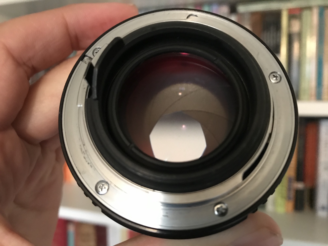
This image shows the exit pupil because it’s seen through the rear element of the lens. A view through the front element would show the entrance pupil.
The f-number of a lens is the ratio of the focal length to the diameter of the aperture, but did you know that it isn’t the actual diameter of the aperture that’s used in this calculation? It’s the apparent diameter as viewed through the front of the lens. A lens might have a magnifying front element, causing the aperture to appear larger than its physical size, or a reducing one, causing it to appear smaller. Either way, it’s this apparent aperture – known as the entrance pupil – which is used to find the f-number.
2. No-parallax point
The no-parallax point of a lens is located at its entrance pupil. Sometimes called the nodal point, although that’s technically something different, this is the point around which the camera must pan and tilt if you want to eliminate all parallax. This is important for forced perspective work, for panoramas stitched together from multiple shots, and other types of VFX.
3. Focus
If you need to check your focal distance with a tape measure, many cameras have a handy Phi symbol on the side indicating where the sensor plane is located so that you can measure from that point. But technically you should be measuring to the entrance pupil. The sensor plane marker is just a convenient shortcut because the entrance pupil is in a different place for every lens and changes when the lens is refocused or zoomed. In most cases the depth of field is large enough for the shortcut to give perfectly acceptable results, however.
4. Bokeh shape
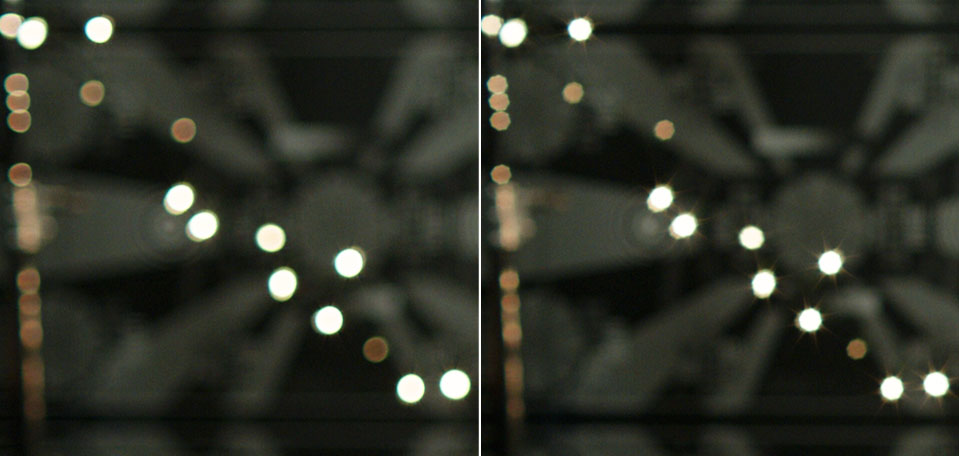
The bokeh of a 32mm Cooke S4 wide open at T2 (left) and stopped down to T2.8 (right). Note also the diffraction spikes visible in the righthand image.
The shape of the entrance pupil determines the shape of the image’s bokeh (out of focus areas), most noticeable in small highlights such as background fairy lights. The pupil’s shape is determined both by the number of iris blades and the shape of their edges. The edges are often curved to approximate a circle when the iris is wide open, but form more of a polygon when stopped down. For example, a Cooke S4 produces octagonal bokeh at most aperture settings, indicating eight iris blades. Incidentally, an anamorphic lens has a roughly circular aperture like any other lens, but the entrance pupil (and hence the bokeh) is typically oval because of the anamorphosing effect of the front elements.
5. Diffraction spikes
When the edge of an iris blade is straight or roughly straight, it spreads out the light in a perpendicular direction, creating a diffraction spike. The result is a star pattern around bright lights, typically most visible at high f-stops. Every blade produces a pair of spikes in opposite directions, so the number of points in the star is equal to twice the number of iris blades – as long as that number is odd. If the number of blades is even, diffraction spikes from opposite sides of the iris overlap, so the number of apparent spikes is the same as the number of blades, as in the eight-pointed Cooke diffraction pictured above right.
So far in this series we have seen how we can adjust exposure using aperture, which affects depth of field, ND filters, which can help us retain the depth of field we want, and shutter angle, which affects motion blur and flickering of certain light sources. In this final part we’ll look at ISO, perhaps the most misunderstood element of exposure, if indeed we can technically classify it as part of exposure at all!
What is ISO?
The acronym stands for International Organization for Standardization, the body which in 1974 combined the old ASA (American Standards Association) units of film speed with the German DIN standard. That’s why you’ll often hear the terms ISO and ASA used interchangeably.
Two different cameras filming the same scene with the same filters, aperture and shutter settings will not necessarily produce an image of equal brightness, because the ways that their electronics convert light into video signals are different. That is why we need ISO, which defines the relationship between the amount of light reaching the sensor (or film) and the brightness of the resulting image.
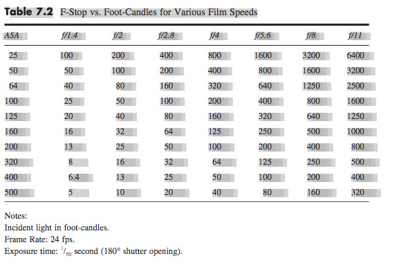
For example, a common ISO to shoot at today is 800. One way of defining ISO 800 is that it’s the setting required to correctly expose a key-light of 12 foot-candles with a lens set to T2.8 and a 180° shutter at 24fps (1/48th of a second).
If we double the ISO we double the effective sensitivity of the camera, or halve the amount of light it requires. So at ISO 1600 we would only need 6 foot-candles of light (all the other settings being the same), and at ISO 3200 we would need just 3 foot-candles. Conversely, at ISO 400 we would need about 25 foot-candles, or 50 at ISO 200.
A Flawed Analogy
Note that I said “effective” sensitivity. This is an important point. In the photochemical world, ISO indeed denotes the light sensitivity of the film stock. It is tempting to see digital ISO as representing the sensitivity of the sensor, and changing the ISO as analogous to loading a different film stock. But in reality the sensitivity of a digital sensor is fixed, and the ISO only determines the amount of gain applied to the sensor data before it is processed (which may happen in camera if you’re shooting linear or log, or in post if you’re shooting RAW).
So a better analogy is that altering the ISO is like altering how long the lab develops the exposed film negative for. This alters the film’s exposure index (EI), hence some digital cameras using the term EI in their menus instead of ISO or ASA.
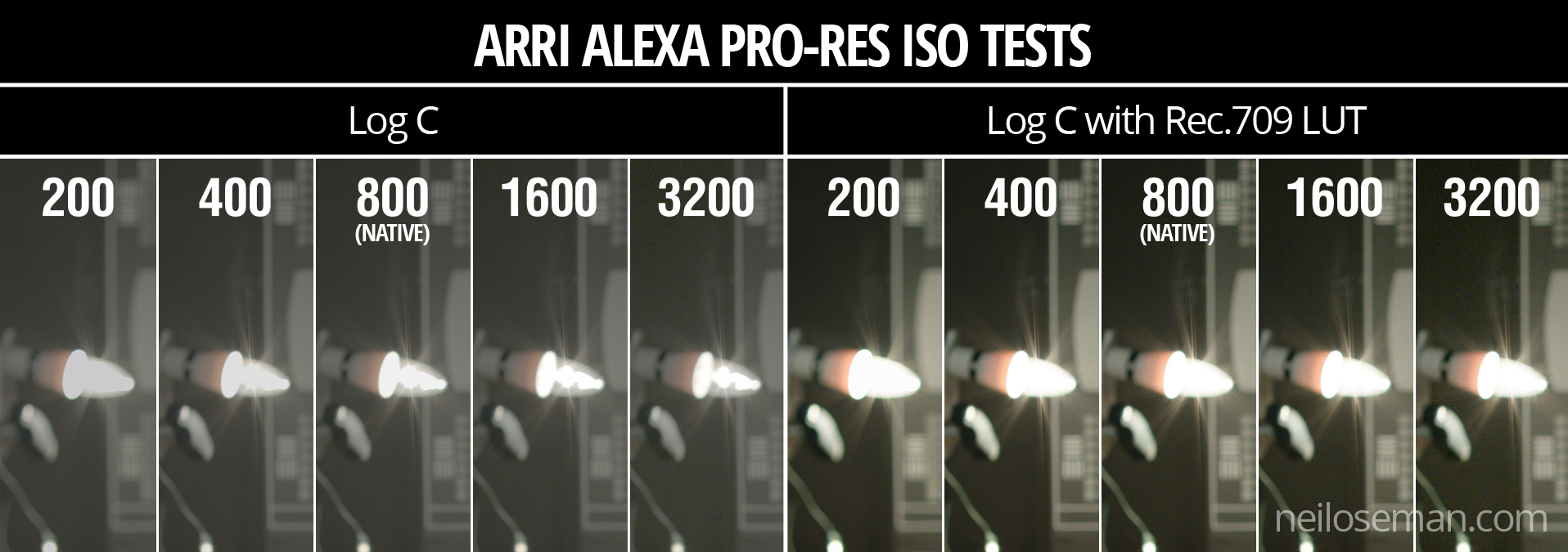
We can take this analogy further. Film manufacturers specify a recommended development time, an arbitrary period designed to produce the optimal image. If you increase (push) or decrease (pull) the development time you will get a lighter or darker image respectively, but the quality of the image will be reduced in various ways. Similarly, digital camera manufacturers specify a native ISO, which is essentially the recommended amount of gain applied to the sensor data to produce what the manufacturer feels is the best image, and if you move away from that native ISO you’ll get a subjectively “lower quality” image.
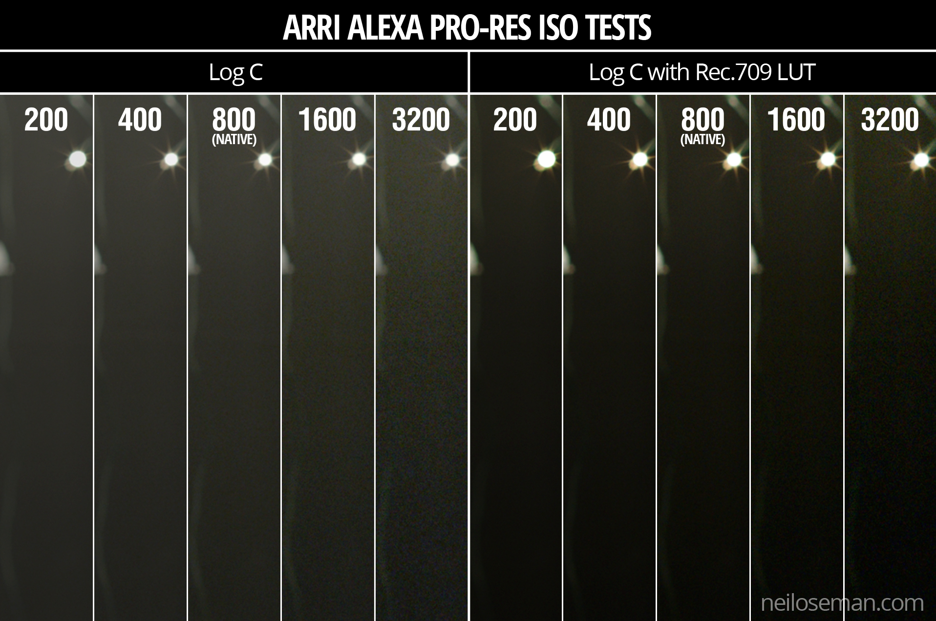
Compare the graininess/smoothness of the blacks in these images from my 2017 tests. Click to enlarge.
The most obvious side effect of increasing the ISO is more noticeable noise in the image. It’s exactly the same as turning up the volume on an amplifier; you hear more hiss because the noise floor is being boosted along with the signal itself.
I remember the days of Mini-DV cameras, which instead of ISO had gain; my Canon XL1 had gain settings of -3dB, +6dB and +12dB. It was the exact same thing, just with a different name. What the XL1 called 0dB of gain was what we call the native ISO today.
ISO and Dynamic range
At this point we need to bring in the concept of dynamic range. Let’s take the Arri Alexa as an example. This camera has a dynamic range of 14 stops. At its native ISO of 800, those 14 stops of dynamic range are equally distributed above and below “correct” exposure (known as middle grey), so you can overexpose by up to seven stops, and underexpose by up to seven stops, without losing detail.
If you change the Alexa’s ISO, those limits of under- and overexposure still apply, but they’re shifted around middle grey. For example, at 400 ISO you have eight stops of detail below middle grey, but only six above it. This means that, assuming you adjust your iris, shutter or filters to compensate for the change in ISO, you can trade-off highlight detail for shadow detail, or vice versa.
Imagine underexposing a shot by one stop and bringing it back up in post. You increase the highlight detail, because you’re letting half the light through to the sensor, reducing the risk of clipped whites, but you also increase the noise when you bring it up in post. This is basically what you’re doing when you increase your ISO, except that if you’re recording in linear or log then the restoration of brightness and increase in gain happen within the camera, rather than in post with RAW.
Note the increased detail in the bulb at higher ISOs. Click to enlarge..
We can summarise all this as follows:
Doubling the ISO…
increases overall brightness by one stop, and
increases picture noise.
Then adjusting the exposure to compensate (e.g. closing the iris one stop)…
restores overall brightness to its original value,
gives you one more stop of detail in the highlights, and
gives you one less stop of detail in the shadows.
Alternatively, halving the ISO…
decreases overall brightness by one stop, and
decreases picture noise.
Then adjusting the exposure to compensate (e.g. opening the iris one stop)…
restores overall brightness to its original value,
gives you one less stop of detail in the highlights, and
gives you one more stop of detail in the shadows.
Conclusion
This brings me to the end of my exposure series. We’ve seen that choosing the “correct” exposure is a balancing act, taking into account not just the intended brightness of the image but also the desired depth of field, bokeh, lens flares, motion blur, flicker prevention, noise and dynamic range. I hope this series has helped you to make the best creative decisions on your next production.
In the first two parts of this series we saw how exposure can be controlled using the lens aperture – with side effects including changes to the depth of field – and neutral density (ND) filters. Today we will look at another means of exposure control: shutter angle.
The Physical Shutters of Film Cameras
As with aperture, an understanding of what’s going on under the hood is useful, and that begins with celluloid. Let’s imagine we’re shooting on film at 24fps, the most common frame rate. The film can’t move continuously through the gate (the opening behind the lens where the focused light strikes the film) or we would end up recording just a long vertical streak of light. The film must remain stationary long enough to expose an image, before being moved on by a distance of four perforations (the standard height of a 35mm film frame) so that the next frame can be exposed. Crucially, light must not hit the film while it is being moved, or vertical streaking will occur.
Joram van Hartingsveldt, CC BY-SA 3.0
This is where the shutter comes in. The shutter is a portion of a disc that spins in front of the gate. The standard shutter angle is 180°, meaning that the shutter is a semi-circle. We always describe shutter angles by the portion of the disc which is missing, so a 270° shutter (admitting 1.5x the light of a 180° shutter) is a quarter of a circle, and a 90° shutter (admitting half the light of a 180° shutter) is three-quarters.
The shutter spins continuously at the same speed as the frame rate – so at 24fps the shutter makes 24 revolutions per second. So with a 180° shutter, each 24th of a second is divided into two halves, i.e. 48ths of a second:
During one 48th of a second, the missing part of the shutter is over the gate, allowing the light to pass through and the stationary film to be exposed.
During the other 48th of a second, the shutter blocks the gate to prevent light hitting the film as it is advanced. The shutter has a mirrored surface so that light from the lens is reflected up the viewfinder, allowing the camera operator to see what they’re shooting.
Intervals vs. Angles
If you come from a stills or ENG background, you may be more used to talking about shutter intervals rather than angles. The two things are related as follows:
For example, 24 x (360 ÷ 180) = 48 so a film running at 24fps, shot with a 180° shutter, shows us only a 48th of a second’s worth of light on each frame. This has been the standard frame rate and shutter angle in cinema since the introduction of sound in the late 1920s. The amount of motion blur captured in a 48th of a second is the amount that we as an audience have been trained to expect from motion pictures all our lives.
A greater (larger shutter angle, longer shutter interval) or lesser (smaller shutter angle, shorter shutter interval) amount of motion blur looks unusual to us and thus can be used to creative effect. Saving Private Ryan features one of the best-known examples of a small shutter angle in its D-day landing sequence, where the lack of motion blur creates a crisp, hyper-real effect that draws you into the horror of the battle. The effect has been endlessly copied since then, to the point that it now feels almost mandatory to shoot action scenes with a small shutter angle.
Large shutter angles are less common, but the extra motion blur can imply a drugged, fatigued or dream-like state.
In today’s digital environment, only the Arri Alexa Studio has a physical shutter. In other cameras, the sensor’s photo-sites are allowed to charge with light over a certain period of time – still referred to as the shutter interval, even though no actual shutter is involved. The same principles apply and the same 180° angle of the virtual shutter is standard. The camera will allow you to select a shutter angle/interval from a number of options, and on some models like the Canon C300 there is a menu setting to switch between displaying the shutter setting as an angle or an interval.
When to Change the Shutter Angle
Sometimes it is necessary to change the shutter angle to avoid flickering. Some luminous devices, such as TV screens and monitors, or HMI lighting not set to flicker-free mode, will appear to strobe, pulse or roll on camera. This is due to them turning on and off multiple times per second, in sync with the alternating current of the mains power supply, but not necessarily in sync with the shutter. For example, if you shoot a domestic fluorescent lamp in the UK, where the mains AC cycles at 50Hz, your 1/48th (180° at 24fps) shutter will be out of sync and the lamp will appear to throb or flicker on camera. The solution is to set the shutter to 172.8° (1/50th), which is indeed what most DPs do when shooting features in the UK. Round multiples of the AC frequency like 1/100th will also work.
You may notice that I have barely mentioned exposure so far in this article. This is because, unlike stills photographers, DPs rarely use the shutter as a means of adjusting exposure. An exception is that we may increase the shutter angle when the daylight is fading, to grab an extra shot. By doubling the shutter angle from 172.8° to 345.6° we double the light admitted, i.e. we gain one stop. As long as there isn’t any fast movement, the extra motion blur is likely to go unnoticed by the audience.
One of the hallmarks of amateur cinematography is that sunny scenes have no motion blur, due to the operator (or the camera’s auto mode) decreasing the shutter interval to avoid over-exposure. It is preferable to use ND filters to cut light on bright days, as covered in part two of this series.
For the best results, the 180° (or thereabouts) shutter angle should be retained when shooting slow motion as well. If your camera displays intervals rather than angles, ideally your interval denominator should be double the frame rate. So if you want to shoot at 50fps, set the shutter interval to 1/100th. For 100fps, set the shutter to 1/200th, and so on.
If you do need to change the shutter angle for creative or technical reasons, you will usually want to compensate with the aperture. If you halve the time the shutter is open for, you must double the area of the aperture to maintain the same exposure, and vice versa. For example, if your iris was set to T4 and you change the shutter from 180° to 90° you will need to stop up to T2.8. (Refer back to my article on aperture if you need to refresh your memory about T-stops.)
In the final part of this series we’ll get to grips with ISO.
Learn more about exposure in my online course, Cinematic Lighting. Until this Thursday (19/11/20) you can get it for the special price of £15.99 by using the voucher code INSTA90.
In the first part of this series, I explained the concepts of f-stops and T-stops, and looked at how aperture can be used to control exposure. We saw that changing the aperture causes side effects, most noticeably altering the depth of field.
How can we set the correct exposure without compromising our depth of field? Well, as we’ll see later in this series, we can adjust the shutter angle and/or ISO, but both of those have their own side effects. More commonly a DP will use neutral density (ND) filters to control the amount of light reaching the lens. These filters get their name from the fact that they block all wavelengths of light equally, so they darken the image without affecting the colour.
When to use an ND Filter
Let’s look at an example. Imagine that I want to shoot at T4; this aperture gives a nice depth of field, on the shallow side but not excessively so. My subject is very close to a bright window and my incident light meter is giving me a reading of f/11. (Although I’m aiming for a T-stop rather an f-stop, I can still use the f-number my meter gives me; in fact if my lens were marked in f-stops then my exposure would be slightly off because the meter does not know the transmission efficiency of my lens.) Let’s remind ourselves of the f-stop/T-stop series before we go any further:
1 1.4 2 2.8 4 5.6 8 11 16 22 32
By looking at this series, which can be found printed on any lens barrel or permanently displayed on a light meter’s screen, I can see that f/11 (or T11) is three stops down from f/4 (or T4) – because 11 is three numbers to the right of 4 in the series. To achieve correct exposure at T4 I’ll need to cut three stops of light. I can often be seen on set counting the stops like this on my light meter or on my fingers. It is of course possible to work it out mathematically or with an app, but that’s not usually necessary. You quickly memorise the series of stops with practice.
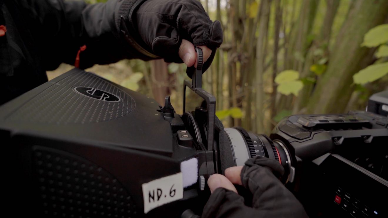
What Strength of filter to choose
Some ND filters are marked in stops, so I could simply select a 3-stop ND and slide it into my matte box or screw it onto my lens. Other times – the built-in ND filters on the Sony FS7, for example – they’re defined by the fraction of light they let through. So the FS7’s 1/4 ND cuts two stops; the first stop halves the light – as we saw in part of one of this series – and the second stop halves it again, leaving us a quarter of the original amount. The 1/16 setting cuts four stops.
However, most commonly, ND filters are labelled in optical density. A popular range of ND filters amongst professional cinematographers are those made by Tiffen, and a typical set might be labelled as follows:
.3 .6 .9 1.2
That’s the optical density, a property defined as the natural logarithm of the ratio of the quantity of light entering the filter to the quantity of light exiting it on the other side. A .3 ND reduces the light by half because 10 raised to the power of -0.3 is about 0.5, and reducing light by half, as we’ve previously established, means dropping one stop.
If that maths is a bit much for you, don’t worry. All you really need to do is multiply the number of stops you want to cut by 0.3 to find the filter you need. So, going back to my example with the bright window, to get from T11 to T4, i.e. to cut three stops, I’ll pick the .9 ND.
It’s far from intuitive at first, but once you get your head around it, and memorise the f-stops, it’s not too difficult. Trust me!
Here are a couple more examples:
Light meter reads f/8 and you want to shoot at T5.6. That’s a one stop difference. (5.6 and 8 are right next to each other in the stop series, as you’ll see if you scroll back to the top.) 1 x 0.3 = 0.3 so you should use the .3 ND.
Light meter reads f/22 and you want to shoot at T2.8. That’s a six stop difference (scroll back up and count them), and 6 x 0.3 = 1.8, so you need a 1.8 ND filter. If you don’t have one, you need to stack two NDs in your matte box that add up to 1.8, e.g. a 1.2 and a .6.
Variations on a Theme
Variable ND filters are also available. These consist of two polarising filters which can be rotated against each other to progressively lighten or darken the image. They’re great for shooting guerilla-style with a small crew. You can set your iris where you want it for depth of field, then expose the image by eye simply by turning the filter. On the down side, they’re hard to use with a light meter because there is often little correspondence between the markings on the filter and stops. They can also have a subtle adverse effect on skin tones, draining a person’s apparent vitality, as some of the light which reflects off human skin is polarised.
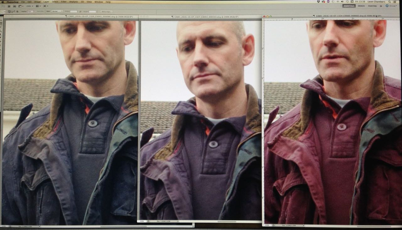
IR pollution increases with successively stronger ND filters (left to right) used on a Blackmagic Micro Cinema Camera. The blue dyes in this costume evidently reflect a large amount of IR.
Another issue to look out for with ND filters is infra-red (IR). Some filters cut only the visible wavelengths of light, allowing IR to pass through. Some digital sensors will interpret this IR as visible red, resulting in an image with a red colour cast which can be hard to grade out because different materials will be affected to different degrees. Special IR ND filters are available to eliminate this problem.
These caveats aside, ND filters are the best way to adjust exposure (downwards at least) without affecting the image in any other way.
In the next part of this series I’ll look at shutter angles, what they mean, how they affect exposure and what the side effects are.
Learn how to use ND filters practically with my Cinematic Lighting online couse. Enter voucher code INSTA90 for an amazing 90% off.
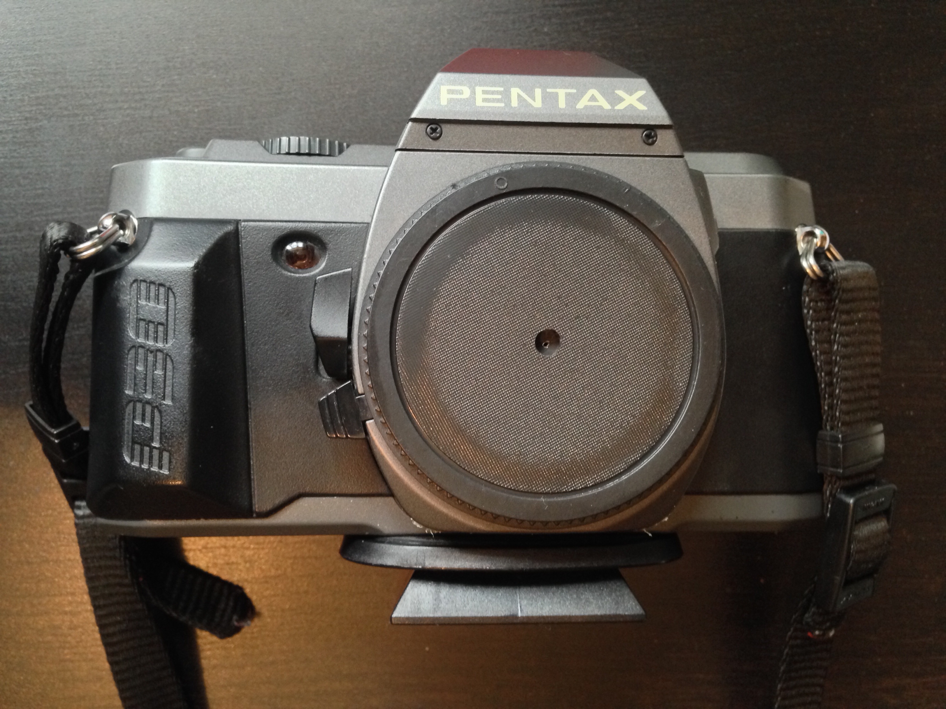
In my last couple of posts I described making and shooting with a pinhole attachment for my 35mm Pentax P30t SLR. Well, the scans are now back from the lab and I’m very pleased with them. They were shot on Fujifilm Superia Xtra 400.
As suspected, the 0.7mm pinhole was far too big, and the results are super-blurry:
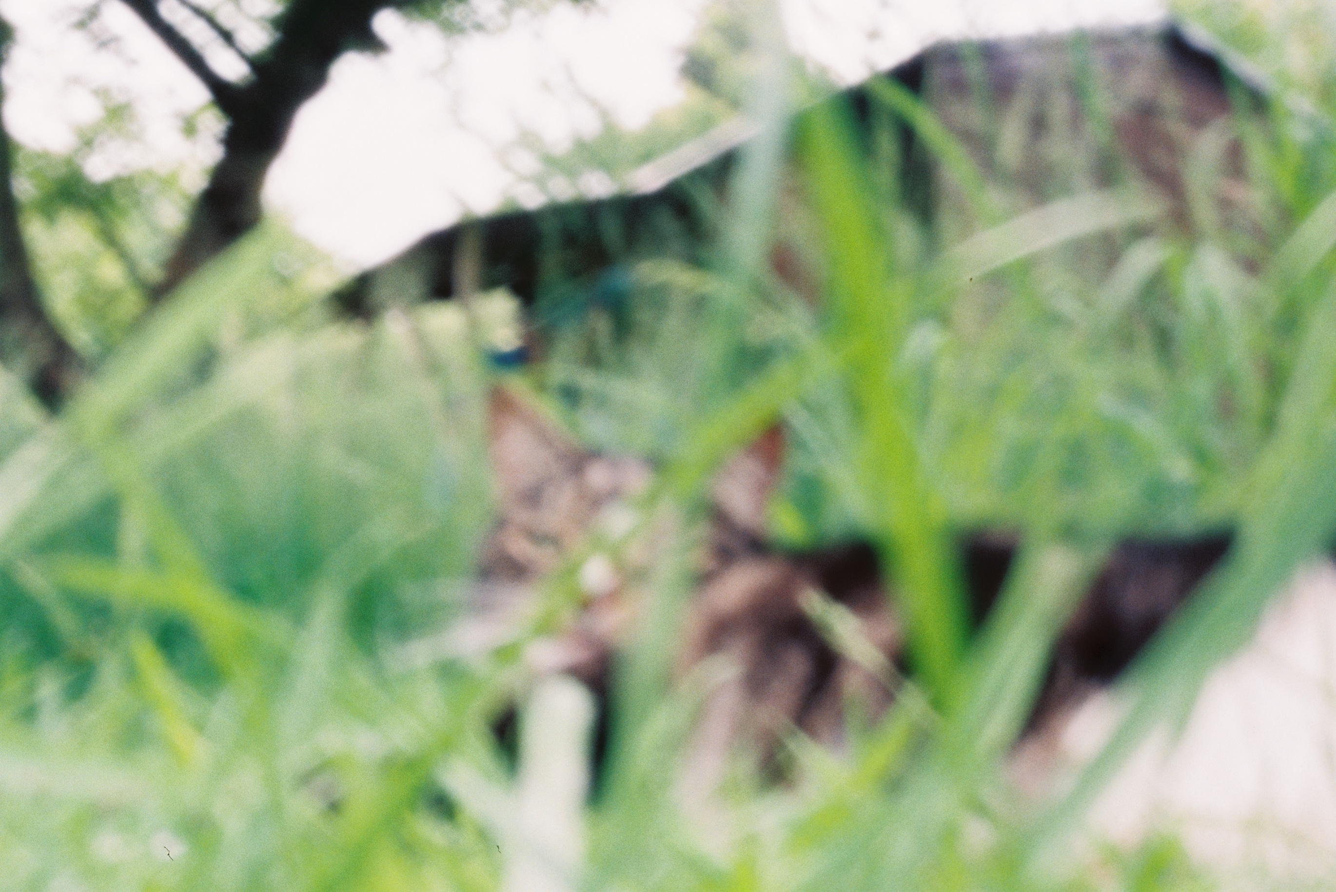
See how contemptuous Spike is of this image. Or maybe that’s just Resting Cat Face.
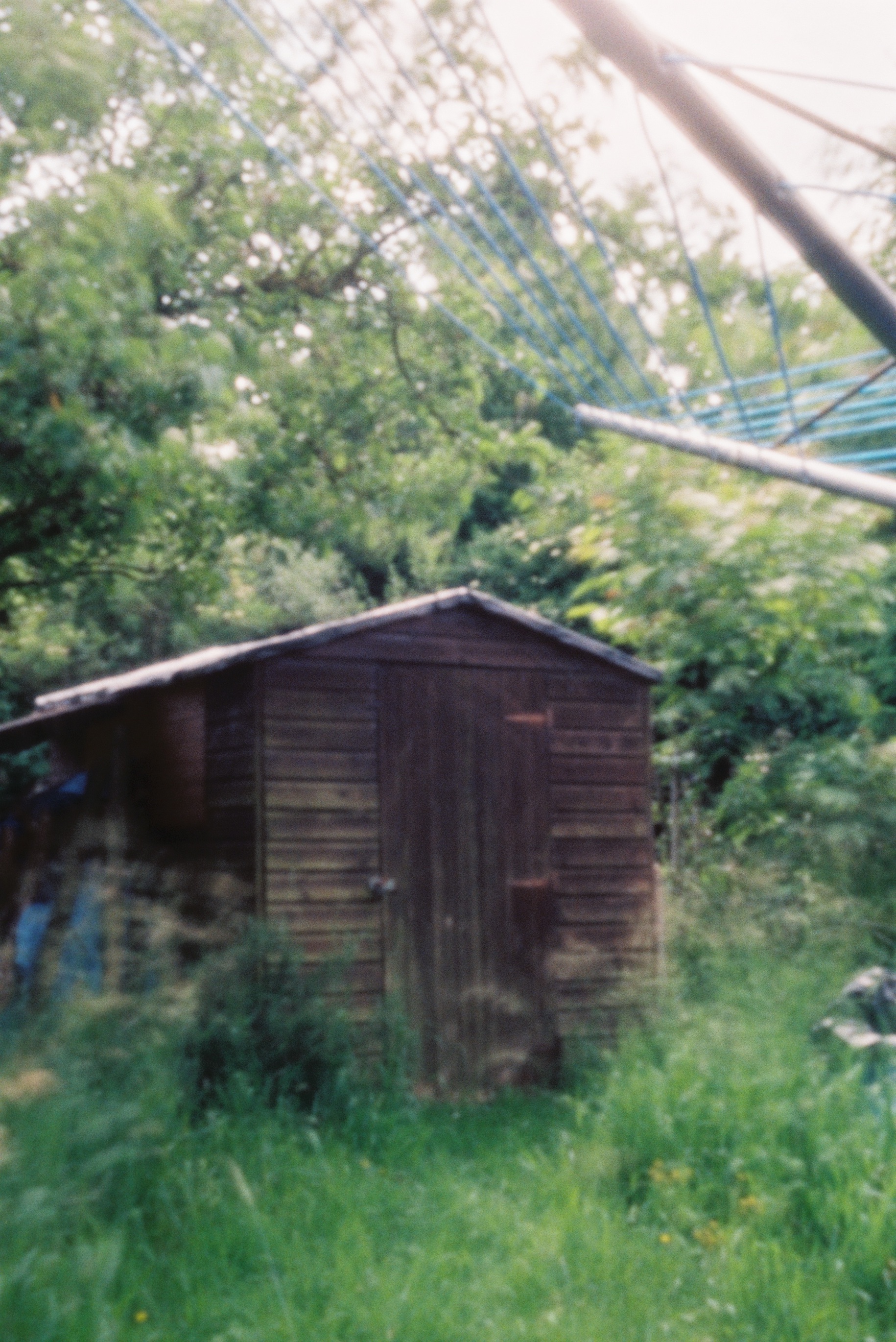
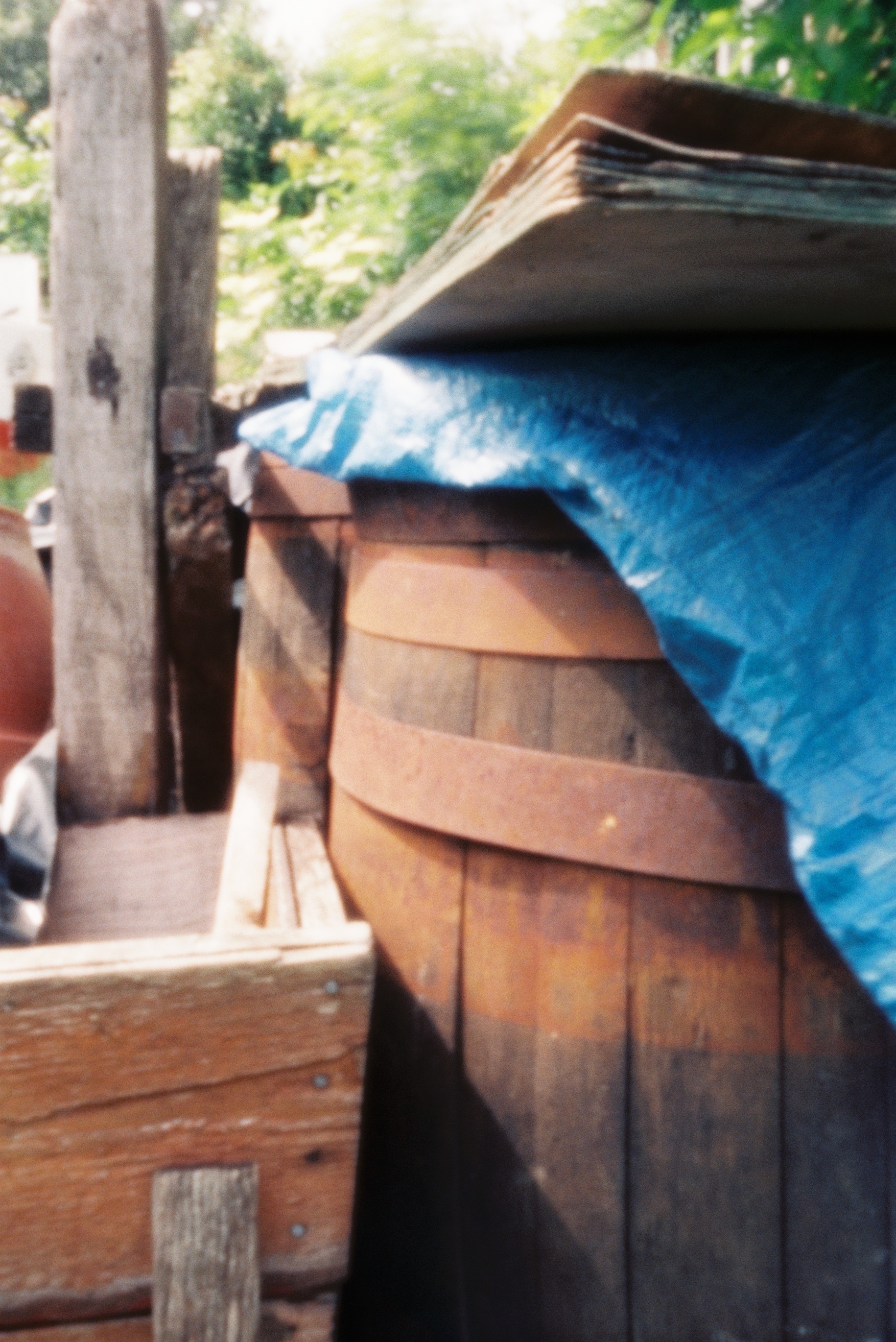
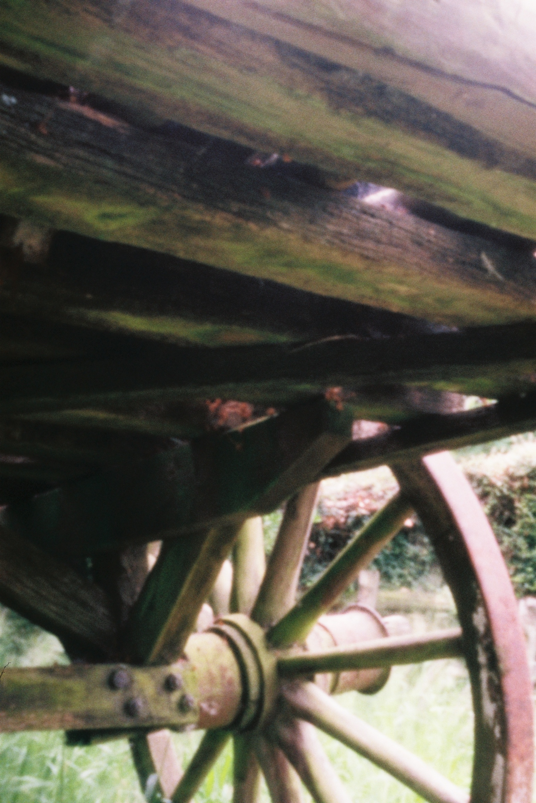
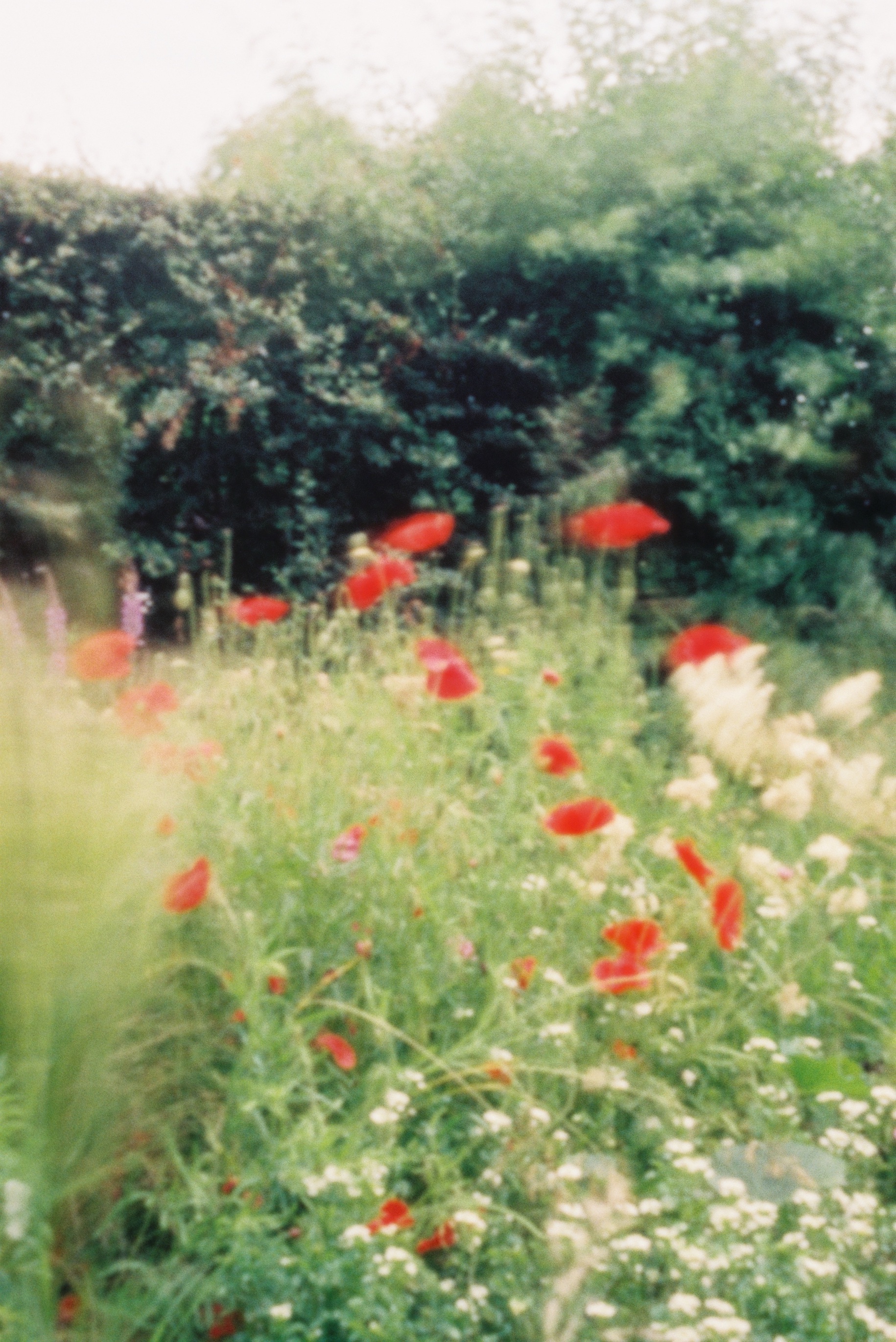
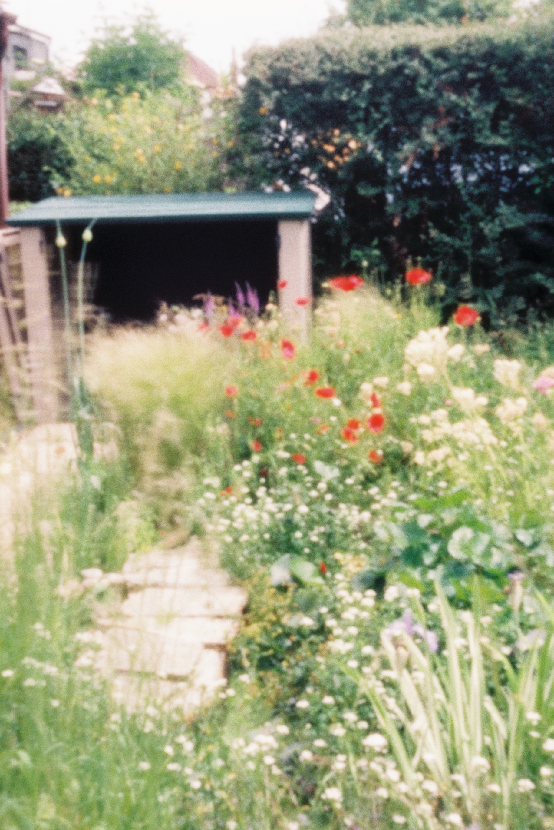
The 0.125mm hole produced much better results, as you can see below. My f/stop calculations (f/365) seem to have been pretty close to the mark, although, as is often the case with film, the occasions where I gave it an extra stop of exposure produced even richer images. Exposure times for these varied between 2 and 16 seconds. Click to see them at higher resolution.
I love the ethereal, haunting quality of all these pictures, which recalls the fragility of Victorian photographs. It’s given me several ideas for new photography projects…
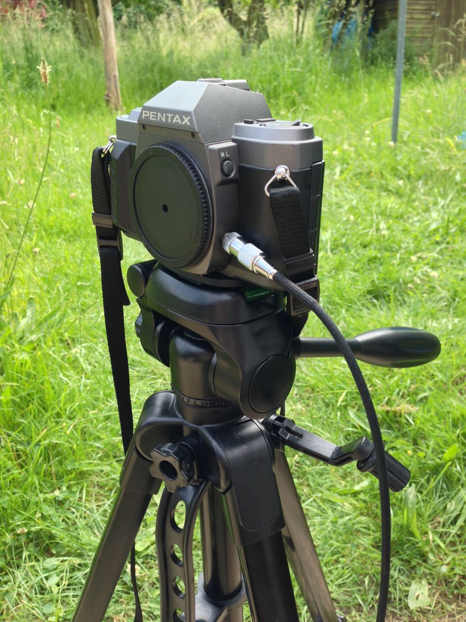
Last week I discussed making a pinhole for my Pentax 35mm SLR. Since then I’ve made a second pinhole and shot a roll of Fujifilm Superia X-tra 400 with them. Although I haven’t had the film processed yet, so the quality of the images is still a mystery, I’ve found shooting with a pinhole to be a really useful exercise.
My Pentax P30T fitted with a 0.125mm pinhole attachment
A Smaller Pinhole
Soon after my previous post, I went out into the back garden and took ten exposures of the pond and the neighbour’s cat with the 0.7mm pinhole. By that point I had decided that the hole was almost certainly too big. As I noted last week, Mr Pinhole gives an optimal diameter of 0.284mm for my camera. Besides that, the (incredibly dark) images in my viewfinder were very blurry, a sign that the hole needed to be smaller.
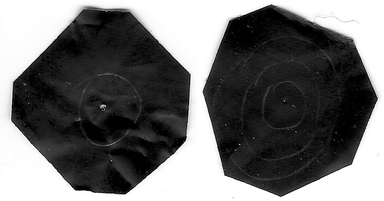
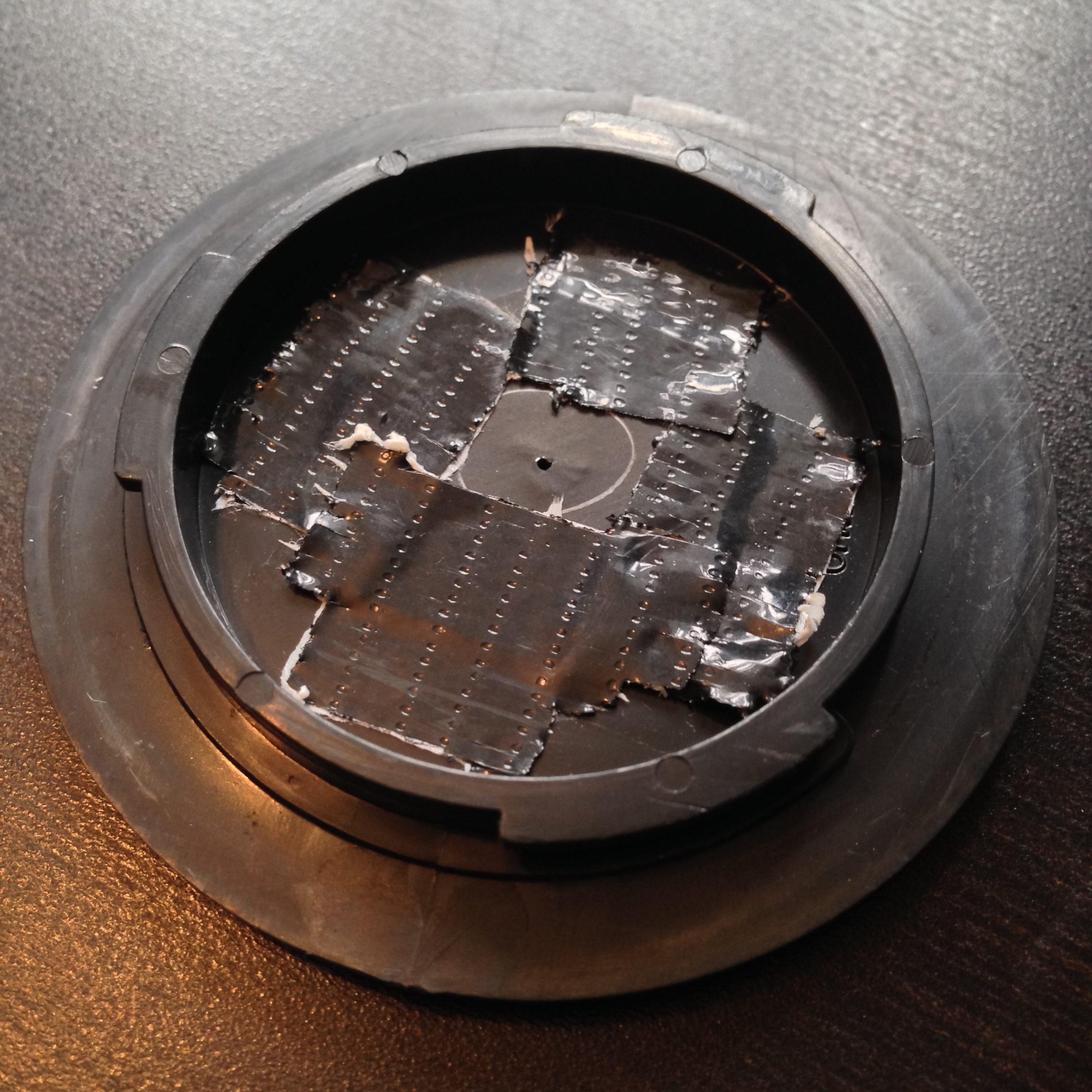
Scans of my two pinholes
So I peeled the piece of black wrap with the 0.7mm pinhole off my drilled body cap and replaced it with another hole measuring about 0.125mm. I had actually made this smaller hole first but rejected it because absolutely nothing was visible through the viewfinder, except for a bit of a blur in the centre. But now I came to accept that I would have to shoot blind if I wanted my images to be anything approaching sharp.
The 0.125mm(ish) pinhole magnified in Photoshop
I had made the 0.125mm hole by tapping the black wrap with only the very tip of the needle, rather than pushing it fully through. Prior to taping it into the body cap, I scanned it at high resolution and measured it using Photoshop. This revealed that it’s a very irregular shape, which probably means the images will still be pretty soft. Unfortunately I couldn’t see a way of getting it any more circular; sanding didn’t seem to help.
Again I found the f-stop of the pinhole by dividing the flange focal distance (45.65mm) by the hole diameter, the result being about f/365. My incident-light meter only goes up to f/90, so I needed to figure out how many stops away from f/365 that is. I’m used to working in the f/1.4-f/22 range, so I wasn’t familiar with how the stop series progresses above f/90. Turns out that you can just multiply by 1.4 to roughly find the next stop up, so after f/90 it’s 128, then 180, then 256, then 358, pretty close to my f/365 pinhole. So whatever reading my meter gave me for f/90, I knew that I would need to add 4 stops of exposure, i.e. multiply the shutter interval by 16. (Stops are a base 2 logarithmic scale. See my article on f-stops, T-stops and ND filters for more info.)
The Freedom of Pinhole Shooting
I’ve just spent a pleasant hour or so in the garden shooting the remaining 26 exposures on my roll with the new 0.125mm pinhole. Regardless of how the photos come out, I found it a fun and fascinating exercise.
Knowing that the images would be soft made me concentrate on colour and form far more than I normally would. Not being able to frame using the viewfinder forced me to visualise the composition mentally. And as someone who finds traditional SLRs very tricky to focus, it was incredibly freeing not to have to worry about that, not to have to squint through the viewfinder at all, but just plonk the camera down where it looked right and squeeze the shutter.
Of course, before squeezing the shutter I needed to take incident-light readings, because the TTL (through the lens) meter was doing nothing but flash “underexposed” at me. Being able to rely solely on an incident meter to judge exposure is a very useful skill for a DP, so this was great practice. I’ve been reading a lot about Ansel Adams and the Zone System lately, and although this requires a spot reflectance meter to be implemented properly, I tried to follow Adams’ philosophy, visualising how I wanted the subject’s tones to correspond to the eventual print tones. (Expect an article about the Zone System in the not-too-distant future!)
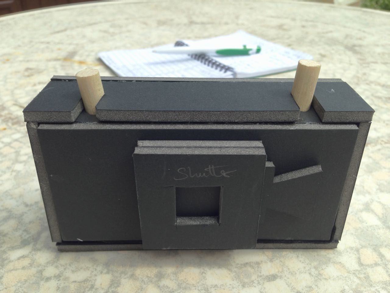
D.I.Y. pinhole Camera
On Tuesday night I went along to a meeting of Cambridge Darkroom, the local camera club. By coincidence, this month’s subject was pinhole cameras. Using online plans, Rich Etteridge had made up kits for us to construct our own complete pinhole cameras in groups. I teamed up with a philosophy student called Tim, and we glued a contraption together in the finest Blue Peter style. The actual pinholes were made in metal squares cut from Foster’s cans, which are apparently something Rich has in abundance.
DIY pinhole camera
I have to be honest though: I’m quite scared of trying to use it. Look at those dowels. Can I really see any outcome of attempting to load this camera other than a heap of fogged film on the floor? No. I think I’ll stick with my actual professionally-made camera body for now. If the pinhole photos I took with that come out alright, then maaaaaaybe I’ll consider lowering the tech level further and trying out my Blue Peter camera. Either way, big thanks to Rich for taking all that time to produce the kits and talk us through the construction.
Watch this space to find out how my pinhole images come out.
Last autumn, after a few years away from it, I got back into 35mm stills photography. I’ve been reading a lot of books about photography: the art of it, the science and the history too. I’ve even taken a darkroom course to learn how to process and print my own black and white photos.
Shooting stills in my spare time gives me more opportunities to develop my eye for composition, my exposure-judging skills and my appreciation of natural light. Beyond that, I’ve discovered interesting parallels between electronic and photochemical imaging which enhance my understanding of both.
For example, I used to think of changing the ISO on a digital camera as analogous to loading a different film stock into a traditional camera. However, I’ve come to realise it’s more like changing the development time – it’s an after-the-fact adjustment to an already-captured (latent) image. There’s more detail on this analogy in my ISO article at Red Shark News.
The importance of rating an entire roll of film at the same exposure index, as it must all be developed for the same length of time, also has resonance in the digital world. Maintaining a consistency of exposure (or the same LUT) throughout a scene or sequence is important in digital filmmaking because it makes the dailies more watchable and reduces the amount of micro-correction which the colourist has to do down the line.
Anyway, this is all a roundabout way of explaining why I decided to make a pinhole attachment for my SLR this week. It’s partly curiosity, partly to increase my understanding of image-making from first principles.
The pinhole camera is the simplest image-making device possible. Because light rays travel in straight lines, when they pass through a very small hole they emerge from the opposite side in exactly the same arrangement, only upside-down, and thus form an image on a flat surface on the other side. Make that flat surface a sheet of film or a digital sensor and you can capture this image.
How to make a pinhole attachment
I used Experimental Filmmaking: Break the Machine by Kathryn Ramey as my guide, but it’s really pretty straightforward.
You will need:
an extra body cap for your camera,
a drill,
a small piece of smooth, non-crumpled black wrap, or kitchen foil painted black,
scissors,
gaffer tape (of course), and
a needle or pin.
Instructions:
Drill a hole in the centre of the body cap. The size of the hole is unimportant.
Use the pin or needle to pierce a hole in the black wrap, at least a couple of centimetres from the edge.
Cut out a rough circle of the black wrap, with the pinhole in the middle. This circle needs to fit on the inside of the body cap, with the pinhole in the centre of the drilled hole.
Use the gaffer tape to fix the black wrap tightly to the inside of the body cap.
Fit the body cap to your camera.
The smaller the pinhole is, the sharper the image will be, but the darker too. The first pinhole I made was about 0.1-0.2mm in diameter, but when I fitted it to my camera and looked through the viewfinder I could hardly make anything out at all. So I made a second one, this time pushing the pin properly through the black wrap, rather than just pricking it with the tip. (Minds out of the gutter, please.) The new hole was about 0.7mm but still produced an incredibly dark image in the viewfinder.
Exposing a pinhole image
If you’re using a digital camera, you can of course judge your exposure off the live-view screen. Things are a little more complicated if, like me, you’re shooting on film.
In theory the TTL (through the lens) light meter should give me just as reliable a reading as it would with a lens. The problem is that, even with the shutter set to 1 second, and ISO 400 Fujifilm Super X-tra loaded, the meter tells me I’m underexposed. Admittedly the weather has been overcast since I made the pinhole yesterday, so I may get a useful reading when the sun decides to come out again.
Failing that, I can use my handheld incident-light meter to determine the exposure…. once I’ve worked out what the f-stop of my pinhole is.
As I described in my article on aperture settings, the definition of an f-stop is: the ratio of the focal length to the aperture diameter. We’re all used to using lenses that have a clearly defined and marked focal length, but what is the focal length in a pinhole system?
The definition of focal length is the distance between the point where the light rays focus (i.e. converge to a point) and the image plane. So the focal length of a pinhole camera is very simply the distance from the pinhole itself to the film or digital sensor. Since my pinhole is more or less level with the top of the lens mount, the focal length is going to be approximately equal to the camera’s flange focal distance (defined as the distance between the lens mount and the image plane). According to Wikipedia, the flange focal distance for a Pentax K-mount camera is 45.46mm.
So the f-stop of my 0.7mm pinhole is f/64, because 45.64 ÷ 0.7 ≈ 64. Conveniently, f/64 is the highest stop my light meter will handle.
The website Mr Pinhole has a calculator to help you figure this sort of stuff out, and it even tells you the optimal pinhole diameter for your focal length. Apparently this is 0.284mm in my case, so my images are likely to be quite soft.
Anyway, when the sun comes out I’ll take some pictures and let you know how I get on!
After seeing Barry Lyndon (1975) on the big screen this week, I felt compelled to write a blog post about its cinematography. But what aspect of the cinematography? The painterly look? The many zooms? The use of natural light?
What I knew for certain is that I should definitely not write about the entirely candlelit scenes lensed on f/0.7 Nasa glass, because everyone knows that story. However, reading the vintage American Cinematographer article and some other material, I found the details surrounding this groundbreaking use of high-speed lenses so interesting that I decided to do it anyway.
The Vision
Barry Lyndon is the 18th century tale of a low-born Irishman who strives – through various misadventures, and ups and downs of fortune – to become a gentleman. The key visual influence of director Stanley Kubrick and DP John Alcott, BSC were the great painters of the story’s era, such as Vermeer.
Next week’s post will look at this painterly influence in Barry Lyndon more closely, but for now the important thing is the use of candlelight on those classical canvases, and Kubrick’s desire to replicate that look. According to lens expert Ed DiGuilio, who was tasked with adapting the f/0.7 glass for Lyndon, Kubrick “wanted to preserve the natural patina and feeling of these old castles at night as they actually were”.
Typically in movies, a candle in frame may motivate the lighting, but most of the illumination on the actors actually comes from an orange-gelled lamp just out of frame. Kubrick wasn’t interested in shooting Lyndon that way. He wanted all the light in those night interior scenes to genuinely come from the candles themselves.
The Problem
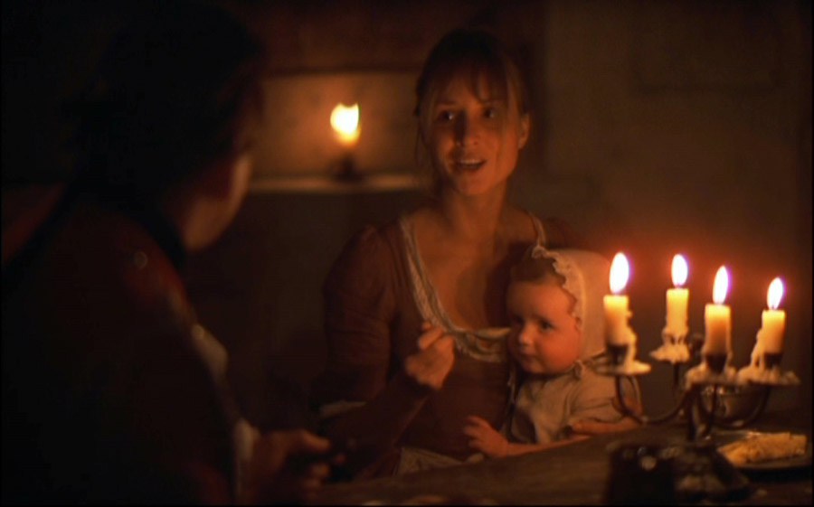
How much light does a candle shed? Conveniently, there is a unit of illumination called the foot-candle. One foot-candle is the amount of light received from a standard candle one foot away. Without going into the detail of what a “standard” candle is, it is enough for our purposes to say that the scene below has a key light of about three foot-candles…
… because there are three candles, about a foot away from the actor’s face. (The level of your key light, and consequently where you set your aperture, is almost always measured at your subject’s face, as that is usually the focus of the shot and the most important thing to get correctly exposed. This is why we DPs are always waving light meters in actors’ faces.)
If we look at an exposure table, such as this one, we can see that a three foot-candle key can be correctly exposed with an aperture of T1.4 and an EI (exposure index) of 800. Today that would be no problem, with many digital cameras having a native EI of 800, and the availability of fast lenses like Zeiss Master Primes and Super Speeds.
In the mid-seventies however, long before the advent of digital cameras, things were not so simple. Kubrick and Alcott had little choice but to shoot on Eastman Kodak 100T 5254. Those first three digits denote the film stock’s exposure index: 100. Alcott pushed the stock (brought the brightness up during processing) one stop, re-rating it to an EI of 200. But it still needed four times more light, or two stops more light than our modern-day Alexa or Red. (Check out my post on f-stops and T-stops if you’re getting lost.)
If we’re losing two stops on the EI, we need to gain two stops on the aperture to compensate. And two stops up from T1.4 is T0.7. You may notice that T0.7 isn’t on that table I linked to. This is because a lens with such a large relative aperture pretty much doesn’t exist.
Pretty much…
The Solution
Kubrick obsessively researched the problem. He eventually discovered that Nasa had commissioned Carl Zeiss to build ten Planar 50mm f/0.7 stills lenses in the sixties, which were used to take photos of the dark side of the moon. (I was unable to find out the T-stop of these lenses, but I’ll assume it was close enough to T0.7 for it to make little difference to my calculations above.) The developments leading to these lenses stretched back through Nazi military applications during WW2 all the way to the late Victorian era, when the double-Gauss cell at the core of the lenses was first invented.
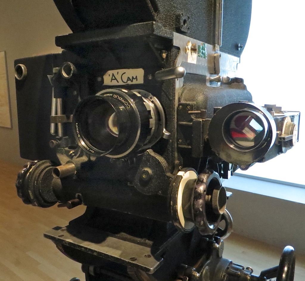
Anyway, Kubrick promptly bought three of the Zeiss Planars. He liked to own equipment himself, rather than hire it in, and to this end he had also purchased at least one Mitchell BNC camera. As befits Kubrick’s perfectionism, these were perhaps the world’s most precisely engineered cameras, previously used for special effects work.
This is where Ed DiGuilio comes in: “[Kubrick] called one day to ask me if I thought I could fit a Zeiss lens he had procured… to his BNC.” It wasn’t simply a case of the f/0.7 glass having the wrong mount. The rear element was so large and needed to be so close to the film plane that DiGuilio had to extensively modify the camera, literally cutting parts out of it.
Ed DiGuilio (left), President of Cinema Products Corporation, working on adapting a zoom lens for Kubrick’s Mitchell BNC
Once this was done, extensive testing ensued. The focus scale (distances marked on the barrel) had to be calibrated from scratch, and indeed the focus ring was re-engineered to allow the precision focusing that the lens’ tiny depth of field would require. Whereas the focus ring on a stills lens will turn about 90° to go from infinity to close focus, and the ring on a cine lens might turn 270°, the rings on these unique Planars now turned a whopping 720° – two whole revolutions!
50mm is a very useful lens length for close-ups, but Kubrick understandably wanted a wider option as well. Accordingly, DiGuilio located an adapter designed to adjust the throw of cinema projector lenses. Mounted onto one of the 50s, it gave an effective focal length of 36.5mm with only very minor light loss. A 24mm version was also tested, but Kubrick disliked the amount of distortion in its images, and rejected it.
The Execution
The colour brown and the trousers of Doug Milsone, Barry Lyndon‘s focus puller, cannot have been strangers to each other. Imagine trying to hold focus on this dolly-back at f/0.7!
By my calculations (which were difficult, because most depth of field tables/calculators don’t go to f/0.7!) an MCU on Kubrick’s 50mm Planar with the subject at 2.5m (8.2ft) and the iris wide open would have had a depth of field of about 43mm (1.7″). To get this same depth of field at f2.8, a popular working stop for cinematographers today, the subject would have to be just 1m (3.3ft) from the sensor plane, which would be a biggish close-up. And remember that focus monitors, peaking and Cine Tape did not exist in the seventies.
To give Milsone a fighting chance, a unique system of focus assist was developed. While the main camera shot an actor from the front, a CCTV camera captured them in profile. This profile image was piped to a monitor, over which a grid was placed. This grid was marked off with distances so that Milsone could see how much the actor had moved by, far more accurately than judging it by eye from beside the lens.
Another problem thrown up by the low-light cinematography was with the viewfinder. Interestingly, the Mitchell BNC was a non-reflex camera, meaning that it didn’t have a mirror on the shutter, reflecting the image to the viewfinder when the shutter was closed. Instead, the camera body racked over to one side to allow the viewfinder to get an image during line-ups and rehearsals, and when it was actually rolling the operator got their images from a side viewfinder with its own lens – just like in a disposable 35mm stills camera. The original prism-based viewfinder on Kubrick’s Mitchell BNC suffered from far too much light loss for a candlelit image to be visible through it, so it was replaced with a mirror-based viewfinder adapted from a Technicolor camera.
The shots resulting from all of these technical challenges are quite soft to the modern eye, but I think that only adds to their beauty. Barry Lyndon captured the exquisite fragility of candelight, and 42 years on the images are still unique and captivating.