“Red Dwarf VI”: Making a Sci-fi Sitcom in 1993

I have been a huge fan of the British sci-fi sitcom Red Dwarf since the age of 12 or 13. The show has undergone many changes over the years, and every fan has their own view about which era is the best, but for me seasons V and VI will always be my favourites. I discovered the show during season V and I remember the huge anticipation for the next season. During this time the show’s production values were very high but it was still extremely funny, with the main characters all well established and well rounded.

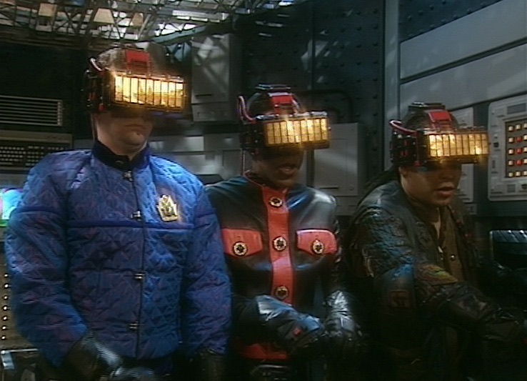
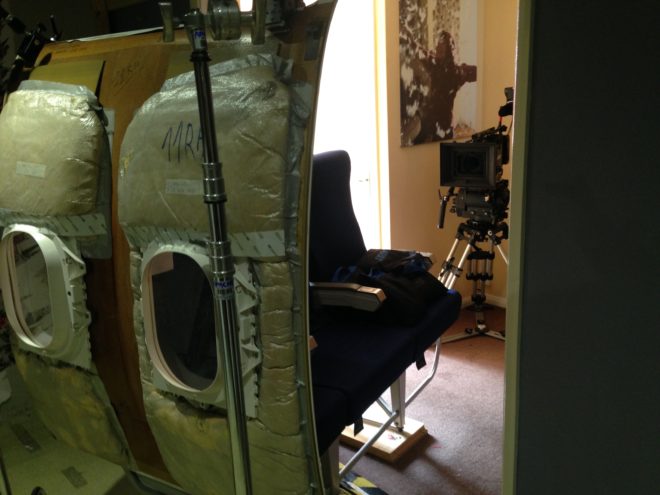
So I was delighted to come across Joe Nazzaro’s book The Making of Red Dwarf in a charity shop recently. It focuses on the production of the series’ most lauded episode, the International Emmy-winning “Gunmen of the Apocalypse” from 1993. The episode sees mechanoid Kryten deliberately contract a computer virus in order to save the Red Dwarf posse, and their efforts to help him battle the infection within the framework of a Wild West VR game representing his consciousness.

What I find fascinating is that the series, at that time at least, was made in such a different way to modern high-end TV or film, following instead the multi-camera sitcom pattern of rehearsing all week and recording in the evening on Saturday.

The cycle began on a Sunday, with production designer Mel Bibby removing the previous episode’s sets from Stage G at Shepperton and installing the new ones.

On Monday the director, writers and cast rehearsed on the set while certain crew members travelled to location – the Laredo Western Club in Kent – to pre-rig. A British sitcom at this time had no director of photography; instead the camera angles were chosen purely by the director and technically executed under the purview of the camera supervisor, while illumination was provided by the lighting director, in this case John Pomphrey. His work at Laredo included putting warm lights inside the buildings to match the look of the interiors which he planned for the studio.

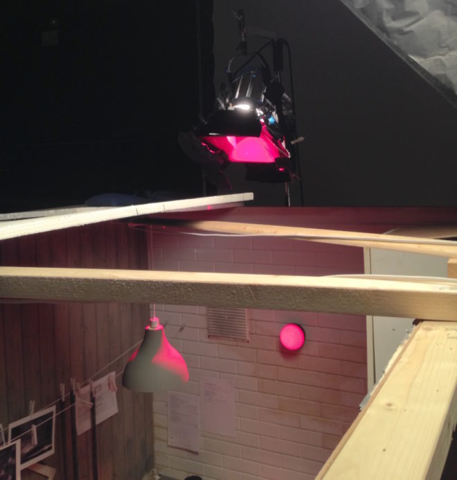
Pomphrey lit a lot of rock and pop shows, and was inspired by concert lighting for such bands as Iron Maiden:

“If you look at them they’re into the same colours I am: oranges, deep blues; powerful colours. I don’t believe in understating something, because you’re generally watching it on a small screen in a well-lit room, so you’ve got to overstate the colours. In the cinema, you can get away with subtle tones, but I don’t think you can on this show… I’m a frustrated cinematographer: I want to make ‘Aliens’.”

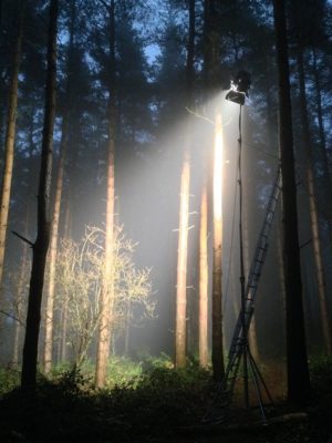
Tuesday was the location shoot, conducted with multiple cameras (though not for every set-up) as director Andy DeEmmony worked through his storyboards. At this time all UK TV was 4:3 standard definition. While a high-end drama would have used 16mm film, most shows, including Red Dwarf, were captured on a tape format like Betacam SP. “Gunmen of the Apocalypse” saw the series make rare use of a crane, and behind-the-scenes photos also show at least one HMI shining through a diffusion frame. It was common practice at this time to use large HMIs to fill in shadows on sunny day exteriors.

On Wednesday rehearsals continued on stage, culminating in a tech run during which camera supervisor Rocket previewed shots using the classic hand-framing method. In the evening the production team convened to discuss the next episode, “Polymorph II: Emohawk”.

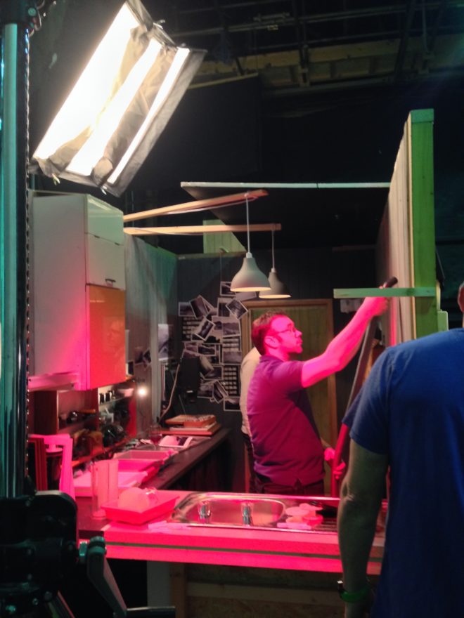
Thursday was known as the Pre-VT day: the day when all scenes too complex to shoot in front of the live audience must be recorded. With “Gunmen” this meant scenes inside the Last Chance Saloon which required such camera tricks as pulling knives out of antagonist Jimmy’s jacket on nylon wires so that in reverse it looked like the knives were pinning him to the wall, Rimmer’s bar fight with four cowboys, and a scene aboard the Simulant ship which is the source of Kryten’s infection.

Pomphrey would communicate by radio with Dai Thomas, who spent studio days in a darkened cabin operating a lighting desk while watching the action on two monitors.

Friday saw more rehearsals, while Tuesday and Thursday’s footage was edited to show to the live audience tomorrow.

Saturday began with blocking and camera rehearsals, before the doors opened to the public at 7pm and recording commenced at 7:30.

It seems that Shepperton Stage G was not equipped with a gallery like a dedicated TV studio; instead, vision mixing was done from the scanner – an outside broadcast truck. For those who don’t know, vision mixing is live editing, cutting from one camera to another in real time as a production assistant calls the shots from the director’s camera script. Elsewhere in the scanner, an engineer monitored the images, doing something akin to the job of a modern DIT, adjusting colours, sharpness and even remotely controlling the cameras’ irises. (Zoom and focus were controlled by the camera operators.)

It’s a testament to all concerned that the show looked so cinematic despite being made this way. Later seasons became even more cinematic, doing away with the live audience for a little while, then bringing it back and later kick-starting Ed Moore BSC’s career when he shot seasons XI and XII beautifully. By this time the show was produced by Dave (a channel named, appropriately enough, after Red Dwarf‘s slobbish hero Dave Lister). It was now captured in HD, on Red cameras of some flavour if I remember rightly, with a focus puller for each one and a more film-like crew structure .

It’s unclear at present if any more seasons will follow 2020’s “The Promised Land”, but if they do I’m sure the series will continue to evolve and embrace new technologies and working practices. Which is a very dull way to end a post about a very funny show, so instead I’ll leave you with one of my favourite jokes from the series, which will make no sense whatsoever unless you remember the set-up.

Kryten, no kitchen appliance should give a human being a double polaroid.

“Red Dwarf VI”: Making a Sci-fi Sitcom in 1993

“Annabel Lee”: Using a Wall as a Light Source

Here’s another lighting breakdown from the short film Annabel Lee, which has won many awards at festivals around the world, including seven now for Best Cinematography.

I wanted the cottage to feel like a safe place for Annabel and E early in the film. When they come back inside and discuss going to the village for food, I knew I wanted a bright beam of sunlight coming in somewhere. I also knew that, as is usual for most DPs in most scenes, I wanted the lighting to be short-key, i.e. coming from the opposite of the characters’ eye-lines to the camera. The blocking of the scene made this difficult though, with Annabel and E standing against a wall and closed door. In the story the cottage does not have working electricity, so I couldn’t imply a ceiling light behind them to edge them out from the wall. Normally I would have suggested to the director, Amy Coop, that we flip things around and wedge the camera in between the cast and the wall so that we could use the depth of the kitchen as a background and the kitchen window as the source of key-light. But it had been agreed with the art department that we would never show the kitchen, which had not been dressed and was full of catering supplies.

The solution was firing a 2.5K HMI in through one of the dining room windows to create a bright rectangle of light on the white wall. This rectangle of bounce became the source of key-light for the scene. We added a matt silver bounce board just out of the bottom of frame on the two-shot, and clamped silver card to the door for the close-ups, to increase the amount of bounce. The unseen kitchen window (behind camera in the two-shot) was blacked out to create contrast. I particularly like E’s close-up, where the diffuse light coming from the HMI’s beam in the haze gives him a lovely rim (stop sniggering).

Adding to the fun was the fact that it was a Steadicam scene. The two-shot had to follow E through into the dining room, almost all of which would be seen on camera, and end on a new two-shot. We put our second 2.5K outside the smaller window (camera left in the shot below), firing through a diffusion frame, to bring up the level in the room. I think we might have put an LED panel outside the bigger window, but it didn’t really do anything useful without coming into shot.

For more on the cinematography of Annabel Lee, visit these links:

“Annabel Lee”: Using a Wall as a Light Source

“Annabel Lee”: Lighting the Arrival

Last week, Annabel Lee – a short I photographed at the end of 2018 – won its sixth and seventh cinematography awards, its festival run having been somewhat delayed by Covid. I’ve previously written a couple of posts around shooting specific parts of Annabel Lee – here’s one about a Steadicam shot with a raven, and another about the church scene – and today I want to dissect the clip above. The sequence sees our two young refugees, Annabel and E, arriving at the Devonshire cottage where they’ll await passage to France.

I was a last-minute replacement for another DP who had to pull out, so the crew, kit list and locations were all in place when I joined. Director Amy Coop had chosen to shoot on an Alexa Mini with Cooke anamorphic glass, and gaffer Bertil Mulvad and the previous DP had put together a package including a nine-light Maxi Brute, a couple of 2.5K HMIs and some LiteMats.

The Brute is serving as the moon in the exteriors, backlighting the (special effects) rain at least when we’re looking towards the driver. (If you’re not familiar with Maxi Brutes, they’re banks of 1K tungsten pars. Ours was gelled blue and rigged on a cherry-picker.) The topography of the location made it impossible to cheat the backlight around when we shot towards Annabel and E; rain doesn’t show up well unless it’s backlit, so this was quite frustrating.

We didn’t have any other sources going on except the period car’s tungsten headlights. It was very tricky to get the cast to hit the exact spots where the headlights would catch them while not shadowing themselves as they held out their hands with umbrellas or brooches.

Inside the cottage it’s a story point that the electricity doesn’t work, so until E lights the oil lamp we could only simulate moonlight and the headlights streaming in through the window. These latter were indeed a simulation, as we didn’t have the picture car at the time we shot inside. There was a whole sequence of bad luck that night when the camera van got stuck on the single-lane dirt track to the cottage, stranding certain crucial vehicles outside and sealing us all inside for three hours after wrap, until the RAC arrived and towed the camera van. So the “headlights” were a couple of tungsten fresnels, probably 650s, which were panned off and dimmed when the car supposedly departs. We also tried to dim them invisibly so that we could get more light on E as he comes in the door and avoid the Close Encounters look when the window comes into shot, but after a few takes of failing to make it undetectable we had to abandon the idea.

We also didn’t have the rain machine for the interiors, so as E opens the door you might briefly glimpse water being poured from an upstairs window by the art department, backlit by an LED panel. We put one of the HMIs outside a window that’s always off camera left to give us some “moonlight” in the room, create colour contrast with the tungsten headlights and the flame of the oil lamp, and ensure that we weren’t left in complete darkness when the “car” departs. Annabel looks right into it as she hugs E.

When the action moves upstairs, an HMI shines in through the window again. I remember it gave us real camera-shadow problems at the end of the scene, because Steadicam operator Rupert Peddle had to end with his back to that window and the talent in front of him (though the clip above cuts off before we get to that bit). The practical oil lamp does a lot of the work making this scene look great. I was sad that I had to put a little fill in the foreground to make E’s bruises at least a tiny bit visible; this was a LiteMat panel set to a very low intensity and bounced off the wall right of camera.

It’s worth mentioning the aspect ratio. My recollection is that I framed for 2.39:1, which is normal for anamorphic shooting. With the Alexa Mini in 4:3 mode, 2x anamorphic lenses produce an 8:3 or 2.66:1 image, which you would typically crop at the sides to 2.39 in post. When I arrived at the grade Annabel Lee was all in 2.66:1 and Amy wanted to keep it that way. I’m not generally a fan of changing aspect ratios in post because it ruins all the composition I worked hard to get right on set, but there’s no denying that this film looks beautiful in the super-wide ratio.

Finally, let me say a huge thank you to all the people who helped make the cinematography the award-winning success it has become, crucially drone operators Mighty Sky, underwater DP Ian Creed and colourist Caroline Morin. I’m sure the judges for these awards were swayed more by the beautiful aerial and aquatic work than the stuff I actually did!

“Annabel Lee”: Lighting the Arrival

The Colour of Moonlight

What colour is moonlight? In cinema, the answer is often blue, but what is the reality? Where does the idea of blue moonlight come from? And how has the colour of cinematic moonlight evolved over the decades?


The science bit

According to universetoday.com the lunar surface “is mostly oxygen, silicon, magnesium, iron, calcium and aluminium”. These elements give the moon its colour: grey, as seen best in photographs from the Apollo missions and images taken from space.

When viewed from Earth, Rayleigh scattering by the atmosphere removes the bluer wavelengths of light. This is most noticeable when the moon is low in the sky, when the large amount of atmosphere that the light has to travel through turns the lunar disc quite red, just as with the sun, while at its zenith the moon merely looks yellow.

Yellow is literally the opposite (or complement) of blue, so where on (or off) Earth did this idea of blue cinematic moonlight come from?

One explanation is that, in low light, our vision comes from our rods, the most numerous type of receptor in the human retina (see my article “How Colour Works” for more on this). These cells are more sensitive to blue than any other colour. This doesn’t actually mean that things look blue in moonlight exactly, just that objects which reflect blue light are more visible than those that don’t.

In reality everything looks monochromatic under moonlight because there is only one type of rod, unlike the three types of cones (red, green and blue) which permit colour vision in brighter situations. I would personally describe moonlight as a fragile, silvery grey.

Blue moonlight on screen dates back to the early days of cinema, before colour cinematography was possible, but when enterprising producers were colour-tinting black-and-white films to get more bums on seats. The Complete Guide to Colour by Tom Fraser has this to say:

As an interesting example of the objectivity of colour, Western films were tinted blue to indicate nighttime, since our eyes detect mostly blue wavelengths in low light, but orange served the same function in films about the Far East, presumably in reference to the warm evening light there.

It’s entirely possible that that choice to tint night scenes blue has as much to do with our perception of blue as a cold colour as it does with the functioning of our rods. This perception in turn may come from the way our skin turns bluer when cold, due to reduced blood flow, and redder when hot. (We saw in my recent article on white balance that, when dealing with incandescence at least, bluer actually means hotter.)

Whatever the reason, by the time it became possible to shoot in colour, blue had lodged in the minds of filmmakers and moviegoers as a shorthand for night.


Examples

Early colour films often staged their night scenes during the day; DPs underexposed and fitted blue filters in their matte boxes to create the illusion. It is hard to say whether the blue filters were an honest effort to make the sunlight look like moonlight or simply a way of winking to the audience: “Remember those black-and-white films where blue tinting meant you were watching a night scene? Well, this is the same thing.”

This scene from “Ben Hur” (1959, DP: Robert Surtees, ASC) appears to be a matte painting combined with a heavily blue-tinted day-for-night shot.
A classic and convincing day-for-night scene from “Jaws” (1975, DP: Bill Butler, ASC)

Day-for-night fell out of fashion probably for a number of reasons: 1. audiences grew more savvy and demanded more realism; 2. lighting technology for large night exteriors improved; 3. day-for-night scenes looked extremely unconvincing when brightened up for TV broadcast. Nonetheless, it remains the only practical way to show an expansive seascape or landscape, such as the desert in Mad Max: Fury Road.

Blue moonlight on stage for “Gone with the Wind” (1939, DP: Ernest Haller)
Cold stage lighting matches the matte-painted mountains in “Black Narcissus” (1947, DP: Jack Cardiff, OBE)

One of the big technological changes for night shooting was the availability of HMI lighting, developed by Osram in the late 1960s. With these efficient, daylight-balanced fixtures large areas could be lit with less power, and it was easy to render the light blue without gels by photographing on tungsten film stock.

Cinematic moonlight reached a peak of blueness in the late 1980s and early ’90s, in keeping with the general fashion for saturated neon colours at that time. Filmmakers like Tony Scott, James Cameron and Jan de Bont went heavy on the candy-blue night scenes.

“Beverly Hills Cop II” (1987, DP: Jeffrey Kimball, ASC)
“Flatliners” (1990, DP: Jan de Bont, ASC)
“Terminator 2: Judgment Day” (1991, DP: Adam Greenberg, ASC) uses a lot of strong, blue light, partly to symbolise the cold inhumanity of the robots, and partly because it’s a hallmark of director James Cameron.

By the start of the 21st century bright blue moonlight was starting to feel a bit cheesy, and DPs were experimenting with other looks.

“The Fast and the Furious” (2001, DP: Ericson Core) has generally warm-coloured night scenes to reflect LA’s mild weather after dark, but often there is a cooler area of moonlight in the deep background.
“War of the Worlds” (2005, DP: Janusz Kaminski, ASC)

Speaking of the above ferry scene in War of the Worlds, Janusz Kaminski, ASC said:

I didn’t use blue for that night lighting. I wanted the night to feel more neutral. The ferryboat was practically illuminated with warm light and I didn’t want to create a big contrast between that light and a blue night look.

The invention of the digital intermediate (DI) process, and later the all-digital cinematography workflow, greatly expanded the possibilities for moonlight. It can now be desaturated to produce something much closer to the silvery grey of reality. Conversely, it can be pushed towards cyan or even green in order to fit an orange-and-teal scheme of colour contrast.

“Pirates of the Carribean: Dead Man’s Chest” (2006, DP: Darius Wolski, ASC)

Darius Wolksi, ASC made this remark to American Cinematographer in 2007 about HMI moonlight on the Pirates of the Caribbean movies:

The colour temperature difference between the HMIs and the firelight is huge. If this were printed without a DI, the night would be candy blue and the faces would be red. [With a digital intermediate] I can take the blue out and turn it into more of a grey-green, and I can take the red out of the firelight and make it more yellow.

Compare Shane Hurlbut, ASC’s moonlight here in “Terminator Salvation” (2009) to the “Terminator 2” shot earlier in the article.
The BBC series “The Musketeers” (2014-2016, pilot DP: Stephan Pehrsson) employed very green moonlight, presumably to get the maximum colour contrast with orange candles and other fire sources.

My favourite recent approach to moonlight was in the Amazon sci-fi series Tales from the Loop. Jeff Cronenweth, ASC decided to shoot all the show’s night scenes at blue hour, a decision motivated by the long dusks (up to 75 minutes) in Winnipeg, where the production was based, and the legal limits on how late the child actors could work.

The results are beautiful. Blue moonlight may be a cinematic myth, but Tales from the Loop is one of the few places where you can see real, naturally blue light in a night scene.

“Tales from the Loop” (2020, DP: Jeff Cronenweth, ASC)

If you would like to learn how to light and shoot night scenes, why not take my online course, Cinematic Lighting? 2,300 students have enrolled to date, awarding it an average of 4.5 stars out of 5. Visit Udemy to sign up now.

The Colour of Moonlight

Exposure Part 3: Shutter

In the first two parts of this series we saw how exposure can be controlled using the lens aperture – with side effects including changes to the depth of field – and neutral density (ND) filters. Today we will look at another means of exposure control: shutter angle.


The Physical Shutters of Film Cameras

As with aperture, an understanding of what’s going on under the hood is useful, and that begins with celluloid. Let’s imagine we’re shooting on film at 24fps, the most common frame rate. The film can’t move continuously through the gate (the opening behind the lens where the focused light strikes the film) or we would end up recording just a long vertical streak of light. The film must remain stationary long enough to expose an image, before being moved on by a distance of four perforations (the standard height of a 35mm film frame) so that the next frame can be exposed. Crucially, light must not hit the film while it is being moved, or vertical streaking will occur.

Joram van Hartingsveldt, CC BY-SA 3.0

This is where the shutter comes in. The shutter is a portion of a disc that spins in front of the gate. The standard shutter angle is 180°, meaning that the shutter is a semi-circle. We always describe shutter angles by the portion of the disc which is missing, so a 270° shutter (admitting 1.5x the light of a 180° shutter) is a quarter of a circle, and a 90° shutter (admitting half the light of a 180° shutter) is three-quarters.

The shutter spins continuously at the same speed as the frame rate – so at 24fps the shutter makes 24 revolutions per second. So with a 180° shutter, each 24th of a second is divided into two halves, i.e. 48ths of a second:

  • During one 48th of a second, the missing part of the shutter is over the gate, allowing the light to pass through and the stationary film to be exposed.
  • During the other 48th of a second, the shutter blocks the gate to prevent light hitting the film as it is advanced. The shutter has a mirrored surface so that light from the lens is reflected up the viewfinder, allowing the camera operator to see what they’re shooting.


Intervals vs. Angles

If you come from a stills or ENG background, you may be more used to talking about shutter intervals rather than angles. The two things are related as follows:

Frame rate x (360 ÷ shutter angle) = shutter interval denominator

For example, 24 x (360 ÷ 180) = 48 so a film running at 24fps, shot with a 180° shutter, shows us only a 48th of a second’s worth of light on each frame. This has been the standard frame rate and shutter angle in cinema since the introduction of sound in the late 1920s. The amount of motion blur captured in a 48th of a second is the amount that we as an audience have been trained to expect from motion pictures all our lives.

A greater (larger shutter angle, longer shutter interval) or lesser (smaller shutter angle, shorter shutter interval) amount of motion blur looks unusual to us and thus can be used to creative effect. Saving Private Ryan features one of the best-known examples of a small shutter angle in its D-day landing sequence, where the lack of motion blur creates a crisp, hyper-real effect that draws you into the horror of the battle. The effect has been endlessly copied since then, to the point that it now feels almost mandatory to shoot action scenes with a small shutter angle.

Large shutter angles are less common, but the extra motion blur can imply a drugged, fatigued or dream-like state.

In today’s digital environment, only the Arri Alexa Studio has a physical shutter. In other cameras, the sensor’s photo-sites are allowed to charge with light over a certain period of time – still referred to as the shutter interval, even though no actual shutter is involved. The same principles apply and the same 180° angle of the virtual shutter is standard. The camera will allow you to select a shutter angle/interval from a number of options, and on some models like the Canon C300 there is a menu setting to switch between displaying the shutter setting as an angle or an interval.


When to Change the Shutter Angle

Sometimes it is necessary to change the shutter angle to avoid flickering. Some luminous devices, such as TV screens and monitors, or HMI lighting not set to flicker-free mode, will appear to strobe, pulse or roll on camera. This is due to them turning on and off multiple times per second, in sync with the alternating current of the mains power supply, but not necessarily in sync with the shutter. For example, if you shoot a domestic fluorescent lamp in the UK, where the mains AC cycles at 50Hz, your 1/48th (180° at 24fps) shutter will be out of sync and the lamp will appear to throb or flicker on camera. The solution is to set the shutter to 172.8° (1/50th), which is indeed what most DPs do when shooting features in the UK. Round multiples of the AC frequency like 1/100th will also work.

You may notice that I have barely mentioned exposure so far in this article. This is because, unlike stills photographers, DPs rarely use the shutter as a means of adjusting exposure. An exception is that we may increase the shutter angle when the daylight is fading, to grab an extra shot. By doubling the shutter angle from 172.8° to 345.6° we double the light admitted, i.e. we gain one stop. As long as there isn’t any fast movement, the extra motion blur is likely to go unnoticed by the audience.

One of the hallmarks of amateur cinematography is that sunny scenes have no motion blur, due to the operator (or the camera’s auto mode) decreasing the shutter interval to avoid over-exposure. It is preferable to use ND filters to cut light on bright days, as covered in part two of this series.

For the best results, the 180° (or thereabouts) shutter angle should be retained when shooting slow motion as well. If your camera displays intervals rather than angles, ideally your interval denominator should be double the frame rate. So if you want to shoot at 50fps, set the shutter interval to 1/100th. For 100fps, set the shutter to 1/200th, and so on.

If you do need to change the shutter angle for creative or technical reasons, you will usually want to compensate with the aperture. If you halve the time the shutter is open for, you must double the area of the aperture to maintain the same exposure, and vice versa. For example, if your iris was set to T4 and you change the shutter from 180° to 90° you will need to stop up to T2.8. (Refer back to my article on aperture if you need to refresh your memory about T-stops.)

In the final part of this series we’ll get to grips with ISO.

Learn more about exposure in my online course, Cinematic Lighting. Until this Thursday (19/11/20) you can get it for the special price of £15.99 by using the voucher code INSTA90.

Exposure Part 3: Shutter

The First Light a Cinematographer Should Put Up

Where do you start, as a director of photography lighting a set? What should be the first brushstroke when you’re painting with light?

I believe the answer is backlight, and I think many DPs would agree with me.

Let’s take the example of a night exterior in a historical fantasy piece, as featured in my online course, Cinematic Lighting. The main source of light in such a scene would be the moon. Where am I going to put it? At the back.

The before image is lit by an LED panel serving purely as a work-light while we rehearsed. It’s not directly above the camera, but off to the right, so the lighting isn’t completely flat, but there is very little depth in the image. Beyond the gate is a boring black void.

The after image completely transforms the viewer’s understanding of the three-dimensional space. We get the sense of a world beyond the gate, an intriguing world lighter than the foreground, with a glimpse of trees and space. Composing the brazier in the foreground has added a further plane, again increasing the three-dimensional impression.

Here is the lighting diagram for the scene. (Loads more diagrams like this can be seen on my Instagram feed.)

The “moon” is a 2.5KW HMI fresnel way back amongst the trees, hidden from camera by the wall on the right. This throws the gate and the characters into silhouette, creating a rim of light around their camera-right sides.

To shed a little light on Ivan’s face as he looks camera-left, I hid a 4×4′ Kino Flo behind the lefthand wall, again behind the actors.

The LED from the rehearsal, a Neewer 480, hasn’t moved, but now it has an orange gel and is dimmed very low to subtly enhance the firelight. Note how the contrasting colours in the frame add to the depth as well.

So I’ll always go into a scene looking at where to put a big backlight, and then seeing if I need any additional sources. Sometimes I don’t, like in this scene from the Daylight Interior module of the course.

Backlight for interior scenes is different to night interiors. You cannot simply put it where you want it. You must work with the position of the windows. When I’m prepping interiors, I always work with the director to try to block the scene so that we can face towards the window as much as possible, making it our backlight. If a set is being built, I’ll talk to the production designer at the design stage to get windows put in to backlight the main camera positions whenever possible.

In the above example, lit by just the 2.5K HMI outside the window, I actually blacked out windows behind camera so that they would not fill in the nice shadows created by the backlight.

Daylight exteriors are different again. I never use artificial lights outdoors in daytime any more. I prefer to work with the natural light and employ reflectors, diffusion or negative fill to mould it where necessary.

So it’s very important to block the scene with the camera facing the sun whenever possible. Predicting the sun path may take a little work, but it will always be worth it.

Here I’ve shot south, towards the low November sun, and didn’t need to modify the light at all.

Shooting in the opposite direction would have looked flat and uninteresting, not to mention causing potential problems with the cast squinting in the sunlight, and boom and camera shadows being cast on them.

You can learn much more about the principles and practice of cinematic lighting by taking my online course on Udemy. Currently you can get an amazing 90% off using the voucher code INSTA90 until November 19th.

For more examples of building a scene around backlight, see my article “Lighting from the Back”.

The First Light a Cinematographer Should Put Up

“Above the Clouds”: The Spoiler Blogs

During 2016-2017 I blogged about the production of Above the Clouds, a comedy road movie which I shot for director Leon Chambers. It premiered at Raindance in 2018, closely followed by Austin Film Festival, where it won the audience award for Best Narrative Feature, the first of four gongs it would collect.

In two decades of filmmaking, Above the Clouds is easily in the top five productions I’m most proud of. Since this January it has been available on AmazoniTunesGoogle Play and other platforms, and I highly recommend you give it a watch. DO NOT continue reading this blog unless you have, because what follows are two blog entries that I held back due to spoilers.


DAY 14

(from Week 3)

The script calls for Charlie to be seen sitting in the window seat of a plane as it rises quite literally above the clouds. This is another micro-set filmed in Leon’s living room, in fact half in the living room and half in the hall, to leave enough room for the lights beyond.

Although the view out of the window will be added in post, I need to simulate the lighting effect of bursting through the clouds. My plan involves a 1.2K HMI, and a 4×4 poly board held horizontally with a triple layer of 4×4 Opal sheets hanging from one edge.

We start with the HMI pointed straight into the window and the poly board held high up so that the Opal hangs in front of the lamp. As the plane supposedly rises through the cloud layer, Colin lowers the poly until it is below the level of the lamp, while Gary tilts the HMI down so its light skips off the poly (like sun skipping off the top of clouds) and bounces back up into the window. Gary then tilts the HMI back up to point straight into the window, to suggest further banking or climbing of the aircraft. This direct light is so hot that it bounces off the armrest of Charlie’s seat and gives a glow to her cheek which syncs perfectly with a smile she’s doing.


DAY 25

(from February 2017 pick-ups)

Today’s set is a dark room. A photographer’s dark room, that is. Not just a random dimly-lit room.

We begin with only the red safe-light in play. The wall-mounted practical has a 15W bulb, so it needs some serious help to illuminate the room. Micky rigs a 1K pup with Medium Red gel and fires it over the top of the set, above the practical. The effect is very convincing. Pure red light can make everything look out of focus on camera, which is why I chose the slightly magenta Medium Red gel, rather than the more realistic Primary Red. The colourist will be able to add some green/yellow to correct this.

During the scene, Naomi pulls a cord and the normal lights come on. These are two hanging practicals, fitted with dimmed 100W tungsten globes. In a very similar set-up to yesterday, we use a 2K with a chimera, poking over the set wall on the camera’s down-side, to enhance and soften the practicals’ light.

To read all the Above the Clouds blogs from the start, click here.

“Above the Clouds”: The Spoiler Blogs

5 Steps to Lighting a Forest at Night

EXT. FOREST - NIGHT

A simple enough slug line, and fairly common, but amongst the most challenging for a cinematographer. In this article I’ll break down into five manageable steps my process of lighting woodlands at night.


1. Set up the moon.

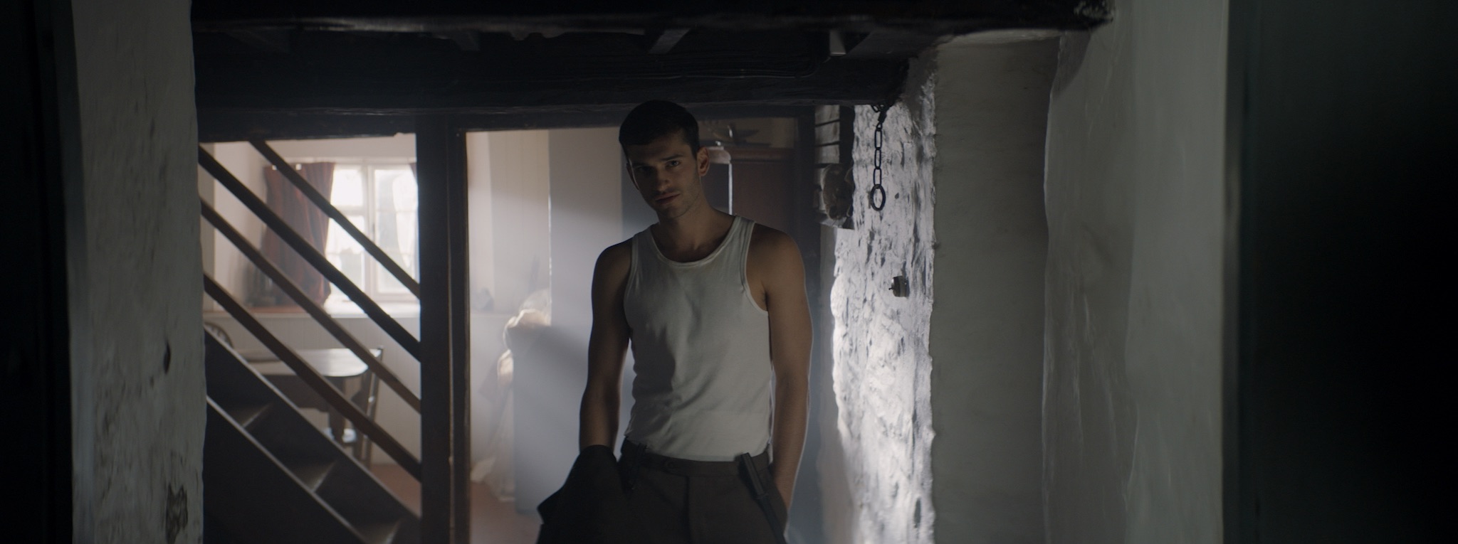
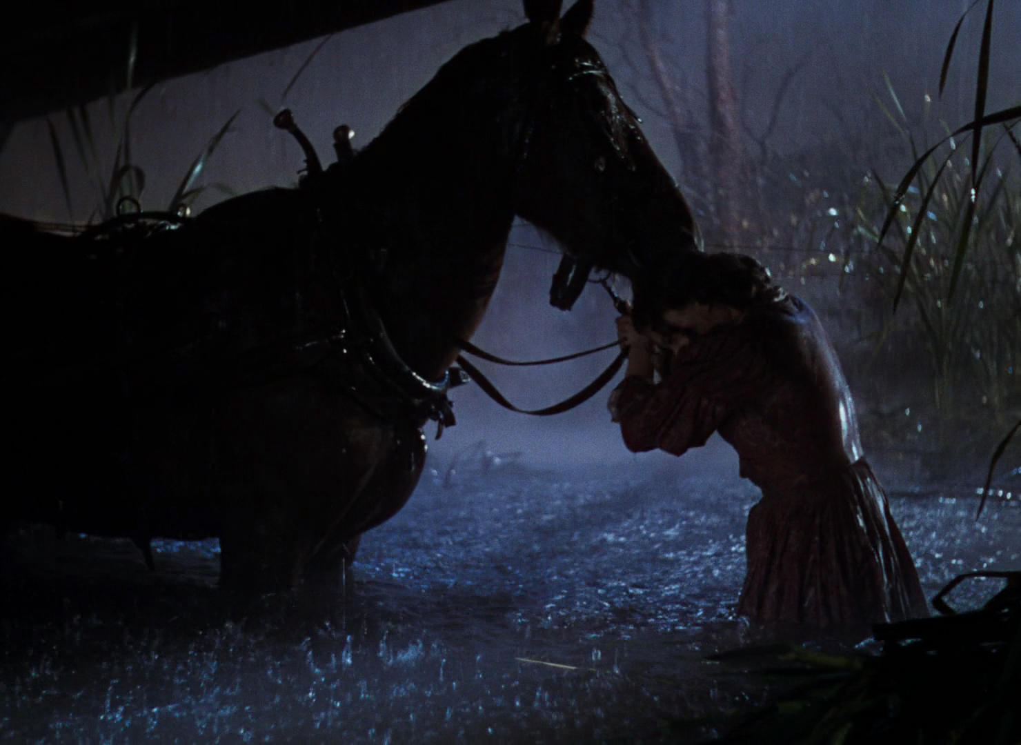
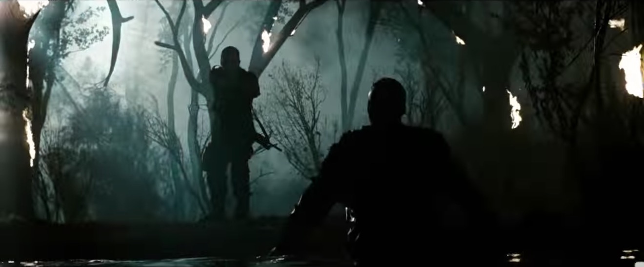
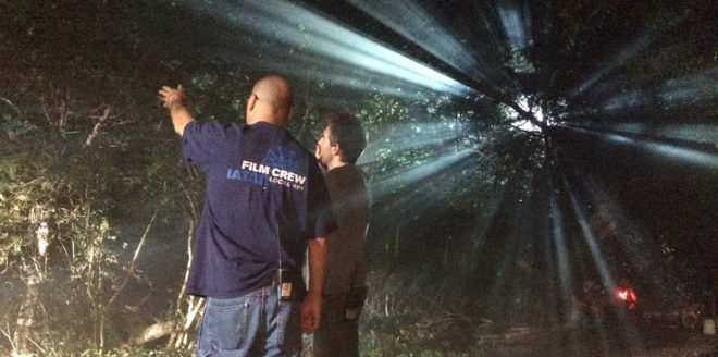
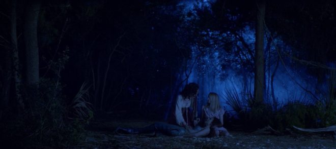
Forests typically have no artificial illumination, except perhaps practical torches carried by the cast. This means that the DP will primarily be simulating moonlight.

Your “moon” should usually be the largest HMI that your production can afford, as high up and far away as you can get it. (If your production can’t afford an HMI, I would advise against attempting night exteriors in a forest.) Ideally this would be a 12K or 18K on a cherry-picker, but in low-budget land you’re more likely to be dealing with a 2.5K on a triple wind-up stand.

Why is height important? Firstly, it’s more realistic. Real moonlight rarely comes from 15ft off the ground! Secondly, it’s hard to keep the lamp out of shot when you’re shooting towards it. A stand might seem quite tall when you’re right next to it, but as soon as you put it far away, it comes into shot quite easily. If you can use the terrain to give your HMI extra height, or acquire scaffolding or some other means of safely raising your light up, you’ll save yourself a lot of headaches.

In this shot from “The Little Mermaid” (dir. Blake Harris), a 12K HMI on a cherry-picker creates the shafts of moonlight, while another HMI through diffusion provides the frontlight. (This frontlight was orange to represent sunrise, but the scene was altered in the grade to be pure night.)

The size of the HMI is of course going to determine how large an area you can light to a sufficient exposure to record a noise-free image. Using a good low-light camera is going to help you out here. I shot a couple of recent forest night scenes on a Blackmagic Pocket Cinema Camera, which has dual native ISOs, the higher being 3200. Combined with a Speedbooster, this camera required only 1 or 2 foot-candles of illuminance, meaning that our 2.5K HMI could be a good 150 feet away from the action. (See also: “How Big a Light do I Need?”)


2. Plan for the reverse.

A fake moon looks great as a backlight, but what happens when it comes time to shoot the reverse? Often the schedule is too tight to move the HMI all the way around to the other side, particularly if it’s rigged up high, so you may need to embrace it as frontlight.

Frontlight is generally flat and undesirable, but it can be interesting when it’s broken up with shadows, and that’s exactly what the trees of a forest will do. Sometimes the pattern of light and dark is so strong and camouflaging that it can be hard to pick out your subject until they move. One day I intend to try this effect in a horror film as a way of concealing a monster.

One thing to look out for with frontlight is unwanted shadows, i.e. those of the camera and boom. Again, the higher up your HMI is, the less of an issue this will be.

If you can afford it, a second HMI set up in the opposite direction is an ideal way to maintain backlight; just pan one off and strike up the other. I’ve known directors to complain that this breaks continuity, but arguably it does the opposite. Frontlight and backlight look very different, especially when smoke is involved (and I’ll come to that in a minute). Isn’t it smoother to intercut two backlit shots than a backlit one and frontlit one? Ultimately it’s a matter of opinion.

An example of cheated moonlight directions in “His Dark Materials” – DP: David Luther


3. Consider Ground lights.

One thing I’ve been experimenting with lately is ground lights. For this you need a forest that has at least a little undulation in its terrain. You set up lights directly on the ground, pointed towards camera but hidden from it behind mounds or ridges in the deep background.

Detail from one of my 35mm stills: pedestrians backlit by car headlights in mist. Shot on Ilford Delta 3200

I once tried this with an HMI and it just looked weird, like there was a rave going on in the next field, but with soft lights it is much more effective. Try fluorescent tubes, long LED panels or even rows of festoon lights. When smoke catches them they create a beautiful glow in the background. Use a warm colour to suggest urban lighting in the distance, or leave it cold and it will pass unquestioned as ambience.

Put your cast in front of this ground glow and you will get some lovely silhouettes. Very effective silhouettes can also be captured in front of smoky shafts of hard light from your “moon”.


4. Fill in the faces.

All of the above looks great, but sooner or later the director is going to want to see the actors’ faces. Such is the cross a DP must bear.

On one recent project I relied on practical torches – sometimes bounced back to the cast with silver reflectors – or a soft LED ball on a boom pole, following the cast around.

Big-budget movies often rig some kind of soft toplight over the entire area they’re shooting in, but this requires a lot of prep time and money, and I expect it’s quite vulnerable to wind.

A recipe that I use a lot for all kinds of night exteriors is a hard backlight and a soft sidelight, both from the same side of camera. You don’t question where the sidelight is coming from when it’s from the same general direction as the “moon” backlight. In a forest you just have to be careful not to end up with very hot, bright trees near the sidelight, so have flags and nets at the ready.

This shot (from a film not yet released, hence the blurring) is backlit by a 2.5K HMI and side-lit by a 1×1 Aladdin LED with a softbox, both from camera right.


5. Don’t forget the Smoke.

Finally, as I’ve already hinted, smoke is very important for a cinematic forest scene. The best options are a gas-powered smoke gun called an Artem or a “Tube of Death”. This latter is a plastic tube connected to a fan and an electric smoke machine. The fan forces smoke into the tube and out of little holes along its length, creating an even spread of smoke.

A Tube of Death in action on the set of “The Little Mermaid”

All smoke is highly suspectible to changes in the wind. An Artem is easier to pick up and move around when the wind changes, and it doesn’t require a power supply, but you will lose time waiting for it to heat up and for the smoke and gas canisters to be changed. Whichever one you pick though, the smoke will add a tremendous amount of depth and texture to the image.

Overall, nighttime forest work scenes may be challenging, but they offer some of the greatest opportunities for moody and creative lighting. Just don’t forget your thermals and your waterproofs!

5 Steps to Lighting a Forest at Night

Colour Rendering Index

Many light sources we come across today have a CRI rating. Most of us realise that the higher the number, the better the quality of light, but is it really that simple? What exactly is Colour Rendering Index, how is it measured and can we trust it as cinematographers? Let’s find out.


What is C.R.I.?

CRI was created in 1965 by the CIE – Commission Internationale de l’Eclairage – the same body responsible for the colour-space diagram we met in my post about How Colour Works. The CIE wanted to define a standard method of measuring and rating the colour-rendering properties of light sources, particularly those which don’t emit a full spectrum of light, like fluorescent tubes which were becoming popular in the sixties. The aim was to meet the needs of architects deciding what kind of lighting to install in factories, supermarkets and the like, with little or no thought given to cinematography.

As we saw in How Colour Works, colour is caused by the absorption of certain wavelengths of light by a surface, and the reflection of others. For this to work properly, the light shining on the surface in the first place needs to consist of all the visible wavelengths. The graphs below show that daylight indeed consists of a full spectrum, as does incandescent lighting (e.g. tungsten), although its skew to the red end means that white-balancing is necessary to restore the correct proportions of colours to a photographed image. (See my article on Understanding Colour Temperature.)

Fluorescent and LED sources, however, have huge peaks and troughs in their spectral output, with some wavelengths missing completely. If the wavelengths aren’t there to begin with, they can’t reflect off the subject, so the colour of the subject will look wrong.

Analysing the spectrum of a light source to produce graphs like this required expensive equipment, so the CIE devised a simpler method of determining CRI, based on how the source reflected off a set of eight colour patches. These patches were murky pastel shades taken from the Munsell colour wheel (see my Colour Schemes post for more on colour wheels). In 2004, six more-saturated patches were added.

The maths which is used to arrive at a CRI value goes right over my head, but the testing process boils down to this:

  1. Illuminate a patch with daylight (if the source being tested has a correlated colour temperature of 5,000K or above) or incandescent light (if below 5,000K).
  2. Compare the colour of the patch to a colour-space CIE diagram and note the coordinates of the corresponding colour on the diagram.
  3. Now illuminate the patch with the source being tested.
  4. Compare the new colour of the patch to the CIE diagram and note the coordinates of the corresponding colour.
  5. Calculate the distance between the two sets of coordinates, i.e. the difference in colour under the two light sources.
  6. Repeat with the remaining patches and calculate the average difference.

Here are a few CRI ratings gleaned from around the web:

Source CRI
Sodium streetlight -44
Standard fluorescent 50-75
Standard LED 83
LitePanels 1×1 LED 90
Arri HMI 90+
Kino Flo 95
Tungsten 100 (maximum)


Problems with C.R.I.

There have been many criticisms of the CRI system. One is that the use of mean averaging results in a lamp with mediocre performance across all the patches scoring the same CRI as a lamp that does terrible rendering of one colour but good rendering of all the others.

Demonstrating the non-continuous spectrum of a fluorescent lamp, versus the continuous spectrum of incandescent, using a prism.

Further criticisms relate to the colour patches themselves. The eight standard patches are low in saturation, making them easier to render accurately than bright colours. An unscrupulous manufacturer could design their lamp to render the test colours well without worrying about the rest of the spectrum.

In practice this all means that CRI ratings sometimes don’t correspond to the evidence of your own eyes. For example, I’d wager that an HMI with a quoted CRI in the low nineties is going to render more natural skin-tones than an LED panel with the same rating.

I prefer to assess the quality of a light source by eye rather than relying on any quoted CRI value. Holding my hand up in front of an LED fixture, I can quickly tell whether the skin tones looks right or not. Unfortunately even this system is flawed.

The fundamental issue is the trichromatic nature of our eyes and of cameras: both work out what colour things are based on sensory input of only red, green and blue. As an analogy, imagine a wall with a number of cracks in it. Imagine that you can only inspect it through an opaque barrier with three slits in it. Through those three slits, the wall may look completely unblemished. The cracks are there, but since they’re not aligned with the slits, you’re not aware of them. And the “slits” of the human eye are not in the same place as the slits of a camera’s sensor, i.e. the respective sensitivities of our long, medium and short cones do not quite match the red, green and blue dyes in the Bayer filters of cameras. Under continuous-spectrum lighting (“smooth wall”) this doesn’t matter, but with non-continuous-spectrum sources (“cracked wall”) it can lead to something looking right to the eye but not on camera, or vice-versa.


Conclusion

Given its age and its intended use, it’s not surprising that CRI is a pretty poor indicator of light quality for a modern DP or gaffer. Various alternative systems exist, including GAI (Gamut Area Index) and TLCI (Television Lighting Consistency Index), the latter similar to CRI but introducing a camera into the process rather than relying solely on human observation. The Academy of Motion Picture Arts and Sciences recently invented a system, Spectral Similarity Index (SSI), which involves measuring the source itself with a spectrometer, rather than reflected light. At the time of writing, however, we are still stuck with CRI as the dominant quantitative measure.

So what is the solution? Test, test, test. Take your chosen camera and lens system and shoot some footage with the fixtures in question. For the moment at least, that is the only way to really know what kind of light you’re getting.

SaveSave

SaveSaveSaveSave

SaveSave

SaveSave

SaveSave

SaveSave

SaveSave

SaveSave

SaveSave

SaveSave

Colour Rendering Index

The Inverse Square Law

If you’ve ever read or been taught about lighting, you’ve probably heard of the Inverse Square Law. It states that light fades in proportion to the square of the distance from the source. But lately I started to wonder if this really applies in all situations. Join me as I attempt to get to the bottom of this…


Knowing the law

The seed of this post was sown almost a year ago, when I read Herbert McKay’s 1947 book The Tricks of Light and Colour, which described the Inverse Square Law in terms of light spreading out. (Check out my post about The Tricks of Light and Colour here.)

But before we go into that, let’s get the Law straight in our minds. What, precisely, does it say? Another excellent book, Gerald Millerson’s Lighting for Television and Film, defines it thusly:

With increased distance, the light emitted from a given point source will fall rapidly, as it spreads over a progressively larger area. This fall-off in light level is inversely proportional to the distance square, i.e. 1/d². Thus, doubling the lamp distance would reduce the light to ¼.

The operative word, for our purposes, is “spreads”.

If you’d asked me a couple of years ago what causes the Inverse Square Law, I probably would have mumbled something about light naturally losing energy as it travels. But that is hogwash of the highest order. Assuming the light doesn’t strike any objects to absorb it, there is nothing to reduce its energy. (Air does scatter – and presumably absorb – a very small amount of light, hence atmospheric haze, but this amount will never be significant on the scale a cinematographer deals with.)

In fact, as the Millerson quote above makes clear, the Inverse Square Law is a result of how light spreads out from its source. It’s purely geometry. In this diagram you can see how fewer and fewer rays strike the ‘A’ square as it gets further and further away from the source ‘S’:

Illustration by Borb, CC BY-SA 3.0

Each light ray (dodgy term, I know, but sufficient for our purposes) retains the same level of energy, and there are the same number of them overall, it’s just that there are fewer of them passing through any given area.

So far, so good.


Taking the Law into my own hands

During season two of my YouTube series Lighting I Like, I discussed Dedo’s Panibeam 70 HMI. This fixture produces collimated light, light of which all the waves are travelling in parallel. It occurred to me that this must prevent them spreading out, and therefore render the Inverse Square Law void.

This in turn got me thinking about more common fixtures – par cans, for example.


Par lamps are so named for the Parabolic Aluminised Reflectors they contain. These collect the light radiated from the rear and sides of the filament and reflect it as parallel rays. So to my mind, although light radiated from the very front of the filament must still spread and obey the Inverse Square Law, that which bounces off the reflector should theoretically never diminish. You can imagine that the ‘A’ square in our first diagram would have the same number of light rays passing through it every time if they are travelling in parallel.

Similarly, fresnel lenses are designed to divert the spreading light waves into a parallel pattern:

Even simple open-face fixtures have a reflector which can be moved back and forth using the flood/spot control, affecting both the spread and the intensity of the light. Hopefully by now you can see why these two things are related. More spread = more divergence of light rays = more fall-off. Less spread = less divergence of light rays = more throw.

So, I wondered, am I right? Do these focused sources disobey the Inverse Square Law?


Breaking the law

To find the answer, I waded through a number of fora.

Firstly, and crucially, everyone agrees that the Law describes light radiated from a point source, so any source which isn’t infinitely small will technically not be governed by the Law. In practice, says the general consensus, the results predicted by the Law hold true for most sources, unless they are quite large or very close to the subject.

If you are using a softbox, a Kinoflo or a trace frame at short range though, the Inverse Square Law will not apply.

The above photometric data for a Filmgear LED Flo-box indeed shows a slower fall-off than the Law predicts. (Based on the 1m intensity, the Law predicts the 2m and 3m intensities as 970÷2²=243 lux and 970÷3²=108 lux respectively.)

A Flickr forum contributor called Severin Sadjina puts it like this:

In general, the light will fall off as 1/d² if the size of the light source is negligible compared to the distance d to the light source. If, on the other hand, the light source is significantly larger than the distance d to the light source, the light will fall off as 1/d – in other words: slower than the Inverse Square Law predicts.

Another contributor, Ftir, claims that a large source will start to follow the Law above distances equal to about five times the largest side of the source, so a 4ft Kinoflo would obey the Law very closely after about 20ft. This claim is confirmed by Wikipedia, citing A. Ryer’s The Light Measurement Handbook.

But what about those pesky parallel light beams from the pars and fresnels?

Every forum had a lot of disagreement on this. Most people agree that parallel light rays don’t really exist in real life. They will always diverge or converge, slightly, and therefore the Law applies. However, many claim that it doesn’t apply in quite the same way.

Diagram from a tutorial PDF on light-measurement.com showing a virtual point source behind the bulb of a torch.

A fresnel, according to John E. Clark on Cinematography.com, can still be treated as a point source, but that point source is actually located somewhere behind the lamp-head! It’s a virtual point source. (Light radiating from a distant point source has approximately parallel rays with consequently negligible fall-off, e.g. sunlight.) So if this virtual source is 10m behind the fixture, then moving the lamp from 1m from the subject to 2m is not doubling the distance (and therefore not quartering the intensity). In fact it is multiplying the distance by 1.09 (12÷11=1.09), so the light would only drop to 84% of its former intensity (1÷1.09²=0.84).

I tried to confirm this using the Arri Photometrics App, but the data it gives for Arri’s fresnel fixtures conforms perfectly with an ordinary point source under the Law, leaving me somewhat confused. However, I did find some data for LED fresnels that broke the Law, for example the Lumi Studio 300:

As you can see, at full flood (bottom graphic) the Law is obeyed as expected; the 8m intensity of 2,500 lux is a quarter of the 4m intensity of 10,000 lux. But when spotted (top graphic) it falls off more rapidly. Again, very confusing, as I was expecting it to fall off less rapidly if the rays are diverging but close to parallel.

A more rapid fall-off suggests a virtual point source somewhere in front of the lamp-head. This was mentioned in several places on the fora as well. The light is converging, so the intensity increases as you move further from the fixture, reaching a maximum at the focal point, then diverging again from that point as per the Inverse Square Law. In fact, reverse-engineering the above data using the Law tells me – if my maths is correct – that the focal point is 1.93m in front of the fixture. Or, to put it another way, spotting this fixture is equivalent to moving it almost 2m closer to the subject. However, this doesn’t seem to tally with the beam spread data in the above graphics. More confusion!

I decided to look up ETC’s Source Four photometrics, since these units contain an ellipsoidal reflector which should focus the light (and therefore create a virtual point source) in front of themselves. However, the data shows no deviation from the Law and no evidence of a virtual point source displaced from the actual source.


I fought the law and the law won

I fear this investigation has left me more confused than when I started! Clearly there are factors at work here beyond what I’ve considered.

However, I’ve learnt that the Inverse Square Law is a useful means of estimating light fall-off for most lighting fixtures – even those that really seem like they should act differently! If you double the distance from lamp to subject, you’re usually going to quarter the intensity, or near as damn it. And that rule of thumb is all we cinematographers need 99% of the time. If in doubt, refer to photometrics data like that linked above.

And if anyone out there can shed any light (haha) on the confusion, I’d be very happy to hear from you!

The Inverse Square Law